HP rp3440 Installation Guide, Seventh Edition - HP 9000 rp3410 and HP 9000 rp3 - Page 68
Applying Standby Power to the Server, Connecting to the LAN, LAN Ports on Server Rear
 |
View all HP rp3440 manuals
Add to My Manuals
Save this manual to your list of manuals |
Page 68 highlights
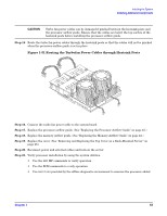
Installing the System Connecting the Cables Applying Standby Power to the Server To apply standby power to the server, follow these steps: Step 1. If the server has one power supply installed in slot P1, plug the power cord into that receptacle. Plug the other end of the power cord into an appropriate outlet. NOTE The LED on the power supply does not illuminate in the standby power state. The LED illuminates when the server is powered on to full power. If the power restore feature is set to Always On through the iLO MP PR command, the server automatically powers on to the full power state when the power cord is plugged into the server. Step 2. If the server has two power supplies, plug the second power cord into the power supply in slot P2. Plug the other end of the power cord into an appropriate outlet. Connecting to the LAN The server has the following ports that provide network connectivity: • iLO MP LAN port. Use this port to access the iLO MP through the LAN. • Console/Remote/UPS port (RS-232). Use this port to access the iLO MP through the console. Figure 1-53 shows the LAN ports on the server rear. Figure 1-53 LAN Ports on Server Rear VGA Port-disabled DO NOT USE Console/Remote/UPS Port (M Cable & RS-232 DB-9F to DB-9F) Serial A/Console Port (factory use only) iLO MP LAN Port (10/100 LAN Cable) 10/100/1000 LAN Port USB Ports (Windows) Mouse & Keyboard Serial B/Console Port (factory use only) To enable general network connectivity for the server, follow these steps: Step 1. Obtain a valid IP address for each LAN port you plan to activate. Step 2. Connect the LAN cable from an available LAN port into a live connection on the network. 68 Chapter 1
-
 1
1 -
2
-
3
-
4
-
5
-
6
-
7
-
8
-
9
-
10
-
11
-
12
-
13
-
14
-
15
-
16
-
17
-
18
-
19
-
20
-
21
-
22
-
23
-
24
-
25
-
26
-
27
-
28
-
29
-
30
-
31
-
32
-
33
-
34
-
35
-
36
-
37
-
38
-
39
-
40
-
41
-
42
-
43
-
44
-
45
-
46
-
47
-
48
-
49
-
50
-
51
-
52
-
53
-
54
-
55
-
56
-
57
-
58
-
59
-
60
-
61
-
62
-
 63
63 -
 64
64 -
 65
65 -
 66
66 -
 67
67 -
 68
68 -
 69
69 -
 70
70 -
 71
71 -
 72
72 -
 73
73 -
74
-
75
-
76
-
77
-
78
-
79
-
80
-
81
-
82
-
83
-
84
-
85
-
86
-
87
-
88
-
89
-
90
-
91
-
92
-
93
-
94
-
95
-
96
 |
 |
