HP rp3440 Installation Guide, Seventh Edition - HP 9000 rp3410 and HP 9000 rp3 - Page 55
Installing an Additional Processor Module, Replacing the Power Supply - cpu
 |
View all HP rp3440 manuals
Add to My Manuals
Save this manual to your list of manuals |
Page 55 highlights
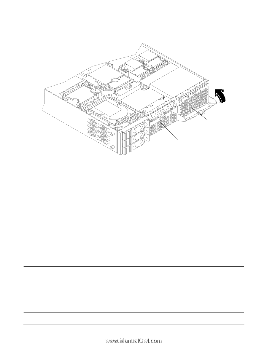
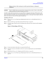
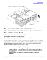
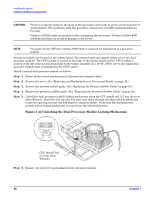
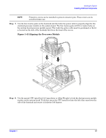
Figure 1-41 Replacing the Power Supply Installing the System Installing Additional Components Power Supply Power Supply 1 Step 4. Push in on the power supply release lever to lock the retaining clip in place. Step 5. Replace the front bezel. (See "Removing and Replacing Front Bezel on a Pedestal-Mounted Server" on page 33.) Step 6. Verify that both power supply LEDs are lit. Step 7. Use the iLO MP PS command to verify power supply operation. Installing an Additional Processor Module This section provides information about installing dual processor modules. The modules are located on the system board which is accessible by removing the server cover. The HP 9000 rp3410 server supports one processor socket. This socket will accept one dual processor module which contains two 800 MHz CPUs. The HP 9000 rp3410 server 1P/1C configuration includes two CPUs in a single module, but only one CPU is enabled. (The second CPU can be enabled as part of a server upgrade.) The HP 9000 rp3440 server supports two processor sockets. Each socket will accept one dual processor module which contains either two 800 MHz CPUs or two 1 GHz CPUs. WARNING Ensure that the server is powered off and all power sources have been disconnected from the server prior to removing or replacing a dual processor module. Voltages are present at various locations within the server whenever an ac power source is connected. This voltage is present even when the main power switch is in the off position. Failure to observe this warning can result in personal injury or damage to equipment. Chapter 1 55
-
 1
1 -
2
-
3
-
4
-
5
-
6
-
7
-
8
-
9
-
10
-
11
-
12
-
13
-
14
-
15
-
16
-
17
-
18
-
19
-
20
-
21
-
22
-
23
-
24
-
25
-
26
-
27
-
28
-
29
-
30
-
31
-
32
-
33
-
34
-
35
-
36
-
37
-
38
-
39
-
40
-
41
-
42
-
43
-
44
-
45
-
46
-
47
-
48
-
49
-
 50
50 -
 51
51 -
 52
52 -
 53
53 -
 54
54 -
 55
55 -
 56
56 -
 57
57 -
 58
58 -
 59
59 -
 60
60 -
61
-
62
-
63
-
64
-
65
-
66
-
67
-
68
-
69
-
70
-
71
-
72
-
73
-
74
-
75
-
76
-
77
-
78
-
79
-
80
-
81
-
82
-
83
-
84
-
85
-
86
-
87
-
88
-
89
-
90
-
91
-
92
-
93
-
94
-
95
-
96
 |
 |