HP t150 Maintenance & Service Guide: HP MultiSeat 6000 Desktop, HP MultiSe - Page 105
Front Bezel Security, Retrieving the Front Bezel Security Screw
 |
View all HP t150 manuals
Add to My Manuals
Save this manual to your list of manuals |
Page 105 highlights
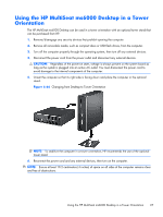
4. Insert the plug end of the security cable into the lock (1) and push the button in (2) to engage the lock. Use the key provided to disengage the lock. Figure 6-63 Engaging the Lock Front Bezel Security The front bezel can be locked in place by installing a security screw provided by HP. To install the security screw: 1. Prepare the computer for disassembly (Preparation for Disassembly on page 42). 2. Remove the access panel (Access Panel on page 43). 3. Remove the front bezel (Front Bezel on page 44). 4. Remove one of the five silver 6-32 standard screws located on the front of the chassis behind the bezel. Figure 6-64 Retrieving the Front Bezel Security Screw 5. Replace the front bezel. External Security Devices 95
-
 1
1 -
2
-
3
-
4
-
5
-
6
-
7
-
8
-
9
-
10
-
11
-
12
-
13
-
14
-
15
-
16
-
17
-
18
-
19
-
20
-
21
-
22
-
23
-
24
-
25
-
26
-
27
-
28
-
29
-
30
-
31
-
32
-
33
-
34
-
35
-
36
-
37
-
38
-
39
-
40
-
41
-
42
-
43
-
44
-
45
-
46
-
47
-
48
-
49
-
50
-
51
-
52
-
53
-
54
-
55
-
56
-
57
-
58
-
59
-
60
-
61
-
62
-
63
-
64
-
65
-
66
-
67
-
68
-
69
-
70
-
71
-
72
-
73
-
74
-
75
-
76
-
77
-
78
-
79
-
80
-
81
-
82
-
83
-
84
-
85
-
86
-
87
-
88
-
89
-
90
-
91
-
92
-
93
-
94
-
95
-
96
-
97
-
98
-
99
-
 100
100 -
 101
101 -
 102
102 -
 103
103 -
 104
104 -
 105
105 -
 106
106 -
 107
107 -
 108
108 -
 109
109 -
 110
110 -
111
-
112
-
113
-
114
-
115
-
116
-
117
-
118
-
119
-
120
-
121
-
122
-
123
-
124
-
125
-
126
-
127
-
128
-
129
-
130
-
131
-
132
-
133
-
134
-
135
-
136
-
137
-
138
-
139
-
140
-
141
-
142
-
143
-
144
-
145
-
146
-
147
-
148
-
149
-
150
-
151
-
152
-
153
-
154
-
155
-
156
-
157
-
158
-
159
-
160
-
161
-
162
-
163
-
164
-
165
-
166
-
167
-
168
-
169
-
170
-
171
-
172
-
173
-
174
-
175
-
176
-
177
-
178
-
179
-
180
-
181
-
182
-
183
-
184
-
185
-
186
-
187
-
188
-
189
-
190
-
191
-
192
-
193
-
194
-
195
-
196
-
197
-
198
-
199
-
200
-
201
-
202
-
203
-
204
-
205
-
206
-
207
-
208
-
209
-
210
-
211
-
212
-
213
-
214
 |
 |
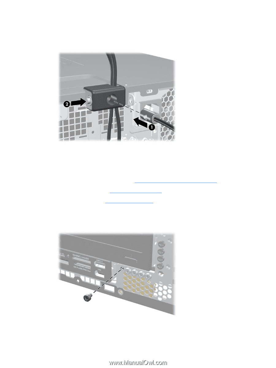
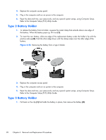
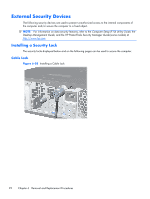
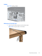
4.
Insert the plug end of the security cable into the lock (1) and push the button in (2) to engage the
lock. Use the key provided to disengage the lock.
Figure 6-63
Engaging the Lock
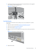
Front Bezel Security
The front bezel can be locked in place by installing a security screw provided by HP. To install the
security screw:
1.
Prepare the computer for disassembly (
Preparation for Disassembly
on page
42
).
2.
Remove the access panel (
Access Panel
on page
43
).
3.
Remove the front bezel (
Front Bezel
on page
44
).
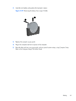
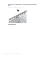
4.
Remove one of the five silver 6-32 standard screws located on the front of the chassis behind the
bezel.
Figure 6-64
Retrieving the Front Bezel Security Screw
5.
Replace the front bezel.
External Security Devices
95