HP t150 Maintenance & Service Guide: HP MultiSeat 6000 Desktop, HP MultiSe - Page 91
Front I/O and Power Switch Assembly,
 |
View all HP t150 manuals
Add to My Manuals
Save this manual to your list of manuals |
Page 91 highlights
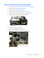
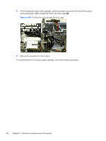
Front I/O and Power Switch Assembly 1. Prepare the computer for disassembly (Preparation for Disassembly on page 42). 2. Remove the access panel (Access Panel on page 43). 3. Remove the front bezel (Front Bezel on page 44). 4. Remove the front fan assembly (Front Fan Assembly on page 80). 5. Remove the black T15 screw (1) that secures the assembly to the chassis. Figure 6-47 Removing the front I/O device/power switch 6. Rotate the drive cage to its upright position. 7. Disconnect the cables (2) from the system board. Figure 6-48 Disconnecting the cables from the system board Front I/O and Power Switch Assembly 81
-
 1
1 -
2
-
3
-
4
-
5
-
6
-
7
-
8
-
9
-
10
-
11
-
12
-
13
-
14
-
15
-
16
-
17
-
18
-
19
-
20
-
21
-
22
-
23
-
24
-
25
-
26
-
27
-
28
-
29
-
30
-
31
-
32
-
33
-
34
-
35
-
36
-
37
-
38
-
39
-
40
-
41
-
42
-
43
-
44
-
45
-
46
-
47
-
48
-
49
-
50
-
51
-
52
-
53
-
54
-
55
-
56
-
57
-
58
-
59
-
60
-
61
-
62
-
63
-
64
-
65
-
66
-
67
-
68
-
69
-
70
-
71
-
72
-
73
-
74
-
75
-
76
-
77
-
78
-
79
-
80
-
81
-
82
-
83
-
84
-
85
-
 86
86 -
 87
87 -
 88
88 -
 89
89 -
 90
90 -
 91
91 -
 92
92 -
 93
93 -
 94
94 -
 95
95 -
 96
96 -
97
-
98
-
99
-
100
-
101
-
102
-
103
-
104
-
105
-
106
-
107
-
108
-
109
-
110
-
111
-
112
-
113
-
114
-
115
-
116
-
117
-
118
-
119
-
120
-
121
-
122
-
123
-
124
-
125
-
126
-
127
-
128
-
129
-
130
-
131
-
132
-
133
-
134
-
135
-
136
-
137
-
138
-
139
-
140
-
141
-
142
-
143
-
144
-
145
-
146
-
147
-
148
-
149
-
150
-
151
-
152
-
153
-
154
-
155
-
156
-
157
-
158
-
159
-
160
-
161
-
162
-
163
-
164
-
165
-
166
-
167
-
168
-
169
-
170
-
171
-
172
-
173
-
174
-
175
-
176
-
177
-
178
-
179
-
180
-
181
-
182
-
183
-
184
-
185
-
186
-
187
-
188
-
189
-
190
-
191
-
192
-
193
-
194
-
195
-
196
-
197
-
198
-
199
-
200
-
201
-
202
-
203
-
204
-
205
-
206
-
207
-
208
-
209
-
210
-
211
-
212
-
213
-
214
 |
 |
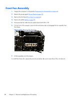
Front I/O and Power Switch Assembly
1.
Prepare the computer for disassembly (
Preparation for Disassembly
on page
42
).
2.
Remove the access panel (
Access Panel
on page
43
).
3.
Remove the front bezel (
Front Bezel
on page
44
).
4.
Remove the front fan assembly (
Front Fan Assembly
on page
80
).
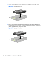
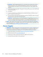
5.
Remove the black T15 screw
(1)
that secures the assembly to the chassis.
Figure 6-47
Removing the front I/O device/power switch
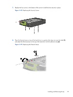
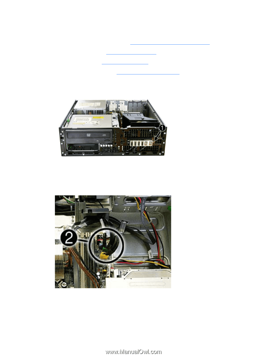
6.
Rotate the drive cage to its upright position.
7.
Disconnect the cables
(2)
from the system board.
Figure 6-48
Disconnecting the cables from the system board
Front I/O and Power Switch Assembly
81