HP t150 Maintenance & Service Guide: HP MultiSeat 6000 Desktop, HP MultiSe - Page 74
CAUTION, Installing Guide Screws in the Optical Drive
 |
View all HP t150 manuals
Add to My Manuals
Save this manual to your list of manuals |
Page 74 highlights
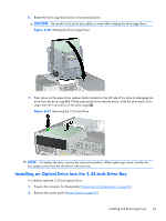
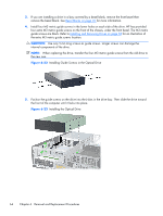
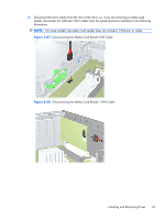
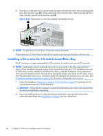
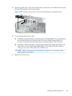
3. If you are installing a drive in a bay covered by a bezel blank, remove the front bezel then remove the bezel blank. See Bezel Blanks on page 45 for more information. 4. Install four M3 metric guide screws in the lower holes on each side of the drive. HP has provided four extra M3 metric guide screws on the front of the chassis, under the front bezel. The M3 metric guide screws are black. Refer to Installing and Removing Drives on page 58 for an illustration of the extra M3 metric guide screws location. CAUTION: Use only 5-mm long screws as guide screws. Longer screws can damage the internal components of the drive. NOTE: When replacing the drive, transfer the four M3 metric guide screws from the old drive to the new one. Figure 6-22 Installing Guide Screws in the Optical Drive 5. Position the guide screws on the drive into the J-slots in the drive bay. Then slide the drive toward the front of the computer until it locks into place. Figure 6-23 Installing the Optical Drive 64 Chapter 6 Removal and Replacement Procedures
-
 1
1 -
2
-
3
-
4
-
5
-
6
-
7
-
8
-
9
-
10
-
11
-
12
-
13
-
14
-
15
-
16
-
17
-
18
-
19
-
20
-
21
-
22
-
23
-
24
-
25
-
26
-
27
-
28
-
29
-
30
-
31
-
32
-
33
-
34
-
35
-
36
-
37
-
38
-
39
-
40
-
41
-
42
-
43
-
44
-
45
-
46
-
47
-
48
-
49
-
50
-
51
-
52
-
53
-
54
-
55
-
56
-
57
-
58
-
59
-
60
-
61
-
62
-
63
-
64
-
65
-
66
-
67
-
68
-
 69
69 -
 70
70 -
 71
71 -
 72
72 -
 73
73 -
 74
74 -
 75
75 -
 76
76 -
 77
77 -
 78
78 -
 79
79 -
80
-
81
-
82
-
83
-
84
-
85
-
86
-
87
-
88
-
89
-
90
-
91
-
92
-
93
-
94
-
95
-
96
-
97
-
98
-
99
-
100
-
101
-
102
-
103
-
104
-
105
-
106
-
107
-
108
-
109
-
110
-
111
-
112
-
113
-
114
-
115
-
116
-
117
-
118
-
119
-
120
-
121
-
122
-
123
-
124
-
125
-
126
-
127
-
128
-
129
-
130
-
131
-
132
-
133
-
134
-
135
-
136
-
137
-
138
-
139
-
140
-
141
-
142
-
143
-
144
-
145
-
146
-
147
-
148
-
149
-
150
-
151
-
152
-
153
-
154
-
155
-
156
-
157
-
158
-
159
-
160
-
161
-
162
-
163
-
164
-
165
-
166
-
167
-
168
-
169
-
170
-
171
-
172
-
173
-
174
-
175
-
176
-
177
-
178
-
179
-
180
-
181
-
182
-
183
-
184
-
185
-
186
-
187
-
188
-
189
-
190
-
191
-
192
-
193
-
194
-
195
-
196
-
197
-
198
-
199
-
200
-
201
-
202
-
203
-
204
-
205
-
206
-
207
-
208
-
209
-
210
-
211
-
212
-
213
-
214
 |
 |