HP t150 Maintenance & Service Guide: HP MultiSeat 6000 Desktop, HP MultiSe - Page 71
System Board Drive Connections,
 |
View all HP t150 manuals
Add to My Manuals
Save this manual to your list of manuals |
Page 71 highlights
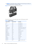
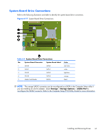
System Board Drive Connections Refer to the following illustration and table to identify the system board drive connectors. Figure 6-17 System Board Drive Connections Table 6-5 System Board Drive Connections No. System Board Connector System Board Label 1 SATA0 SATA0 2 SATA1 SATA1 3 SATA2 SATA2 4 SATA3 SATA3 5 Media Card Reader MEDIA Color dark blue white light blue orange black NOTE: The orange SATA3 connector can be reconfigured as eSATA in the Computer Setup utility if you are installing an eSATA adapter. Select Storage > Storage Options > eSATA Port to reconfigure the SATA3 connector. Refer to the Computer Setup (F10) Utility Guide for more information. Installing and Removing Drives 61
-
 1
1 -
2
-
3
-
4
-
5
-
6
-
7
-
8
-
9
-
10
-
11
-
12
-
13
-
14
-
15
-
16
-
17
-
18
-
19
-
20
-
21
-
22
-
23
-
24
-
25
-
26
-
27
-
28
-
29
-
30
-
31
-
32
-
33
-
34
-
35
-
36
-
37
-
38
-
39
-
40
-
41
-
42
-
43
-
44
-
45
-
46
-
47
-
48
-
49
-
50
-
51
-
52
-
53
-
54
-
55
-
56
-
57
-
58
-
59
-
60
-
61
-
62
-
63
-
64
-
65
-
 66
66 -
 67
67 -
 68
68 -
 69
69 -
 70
70 -
 71
71 -
 72
72 -
 73
73 -
 74
74 -
 75
75 -
 76
76 -
77
-
78
-
79
-
80
-
81
-
82
-
83
-
84
-
85
-
86
-
87
-
88
-
89
-
90
-
91
-
92
-
93
-
94
-
95
-
96
-
97
-
98
-
99
-
100
-
101
-
102
-
103
-
104
-
105
-
106
-
107
-
108
-
109
-
110
-
111
-
112
-
113
-
114
-
115
-
116
-
117
-
118
-
119
-
120
-
121
-
122
-
123
-
124
-
125
-
126
-
127
-
128
-
129
-
130
-
131
-
132
-
133
-
134
-
135
-
136
-
137
-
138
-
139
-
140
-
141
-
142
-
143
-
144
-
145
-
146
-
147
-
148
-
149
-
150
-
151
-
152
-
153
-
154
-
155
-
156
-
157
-
158
-
159
-
160
-
161
-
162
-
163
-
164
-
165
-
166
-
167
-
168
-
169
-
170
-
171
-
172
-
173
-
174
-
175
-
176
-
177
-
178
-
179
-
180
-
181
-
182
-
183
-
184
-
185
-
186
-
187
-
188
-
189
-
190
-
191
-
192
-
193
-
194
-
195
-
196
-
197
-
198
-
199
-
200
-
201
-
202
-
203
-
204
-
205
-
206
-
207
-
208
-
209
-
210
-
211
-
212
-
213
-
214
 |
 |
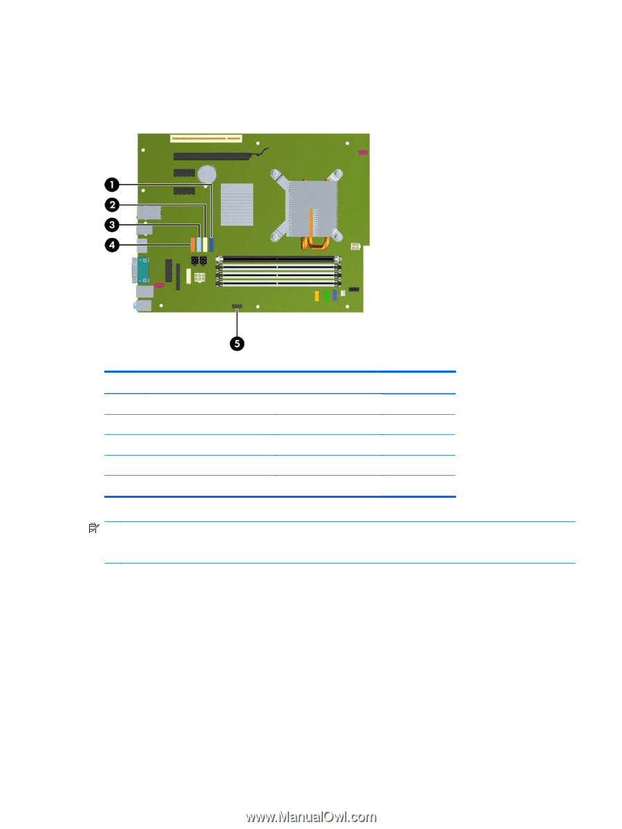
System Board Drive Connections
Refer to the following illustration and table to identify the system board drive connectors.
Figure 6-17
System Board Drive Connections
Table 6-5
System Board Drive Connections
No.
System Board Connector
System Board Label
Color
1
SATA0
SATA0
dark blue
2
SATA1
SATA1
white
3
SATA2
SATA2
light blue
4
SATA3
SATA3
orange
5
Media Card Reader
MEDIA
black
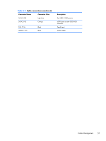
NOTE:
The orange SATA3 connector can be reconfigured as eSATA in the Computer Setup utility if
you are installing an eSATA adapter. Select
Storage
>
Storage Options
>
eSATA Port
to
reconfigure the SATA3 connector. Refer to the
Computer Setup (F10) Utility Guide
for more information.
Installing and Removing Drives
61