HP t150 Maintenance & Service Guide: HP MultiSeat 6000 Desktop, HP MultiSe - Page 90
Front Fan Assembly
 |
View all HP t150 manuals
Add to My Manuals
Save this manual to your list of manuals |
Page 90 highlights
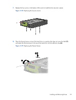
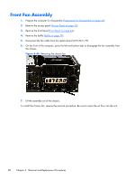
Front Fan Assembly 1. Prepare the computer for disassembly (Preparation for Disassembly on page 42). 2. Remove the access panel (Access Panel on page 43). 3. Remove the front bezel (Front Bezel on page 44). 4. Remove the baffle (Baffle on page 79). 5. Disconnect the fan cable from the system board (CH FAN1, P9). 6. On the front of the computer, press the left and bottom tabs to disengage the fan assembly from the chassis. Figure 6-46 Removing the chassis fan 7. Lift the assembly out of the chassis. To install the chassis fan, reverse the removal procedure. Be sure to orient the air flow into the unit. 80 Chapter 6 Removal and Replacement Procedures
-
 1
1 -
2
-
3
-
4
-
5
-
6
-
7
-
8
-
9
-
10
-
11
-
12
-
13
-
14
-
15
-
16
-
17
-
18
-
19
-
20
-
21
-
22
-
23
-
24
-
25
-
26
-
27
-
28
-
29
-
30
-
31
-
32
-
33
-
34
-
35
-
36
-
37
-
38
-
39
-
40
-
41
-
42
-
43
-
44
-
45
-
46
-
47
-
48
-
49
-
50
-
51
-
52
-
53
-
54
-
55
-
56
-
57
-
58
-
59
-
60
-
61
-
62
-
63
-
64
-
65
-
66
-
67
-
68
-
69
-
70
-
71
-
72
-
73
-
74
-
75
-
76
-
77
-
78
-
79
-
80
-
81
-
82
-
83
-
84
-
 85
85 -
 86
86 -
 87
87 -
 88
88 -
 89
89 -
 90
90 -
 91
91 -
 92
92 -
 93
93 -
 94
94 -
 95
95 -
96
-
97
-
98
-
99
-
100
-
101
-
102
-
103
-
104
-
105
-
106
-
107
-
108
-
109
-
110
-
111
-
112
-
113
-
114
-
115
-
116
-
117
-
118
-
119
-
120
-
121
-
122
-
123
-
124
-
125
-
126
-
127
-
128
-
129
-
130
-
131
-
132
-
133
-
134
-
135
-
136
-
137
-
138
-
139
-
140
-
141
-
142
-
143
-
144
-
145
-
146
-
147
-
148
-
149
-
150
-
151
-
152
-
153
-
154
-
155
-
156
-
157
-
158
-
159
-
160
-
161
-
162
-
163
-
164
-
165
-
166
-
167
-
168
-
169
-
170
-
171
-
172
-
173
-
174
-
175
-
176
-
177
-
178
-
179
-
180
-
181
-
182
-
183
-
184
-
185
-
186
-
187
-
188
-
189
-
190
-
191
-
192
-
193
-
194
-
195
-
196
-
197
-
198
-
199
-
200
-
201
-
202
-
203
-
204
-
205
-
206
-
207
-
208
-
209
-
210
-
211
-
212
-
213
-
214
 |
 |
Front Fan Assembly
1.
Prepare the computer for disassembly (
Preparation for Disassembly
on page
42
).
2.
Remove the access panel (
Access Panel
on page
43
).
3.
Remove the front bezel (
Front Bezel
on page
44
).
4.
Remove the baffle (
Baffle
on page
79
).
5.
Disconnect the fan cable from the system board (CH FAN1, P9).
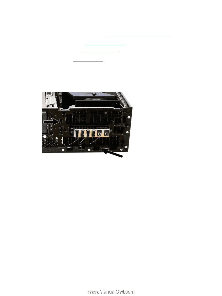
6.
On the front of the computer, press the left and bottom tabs to disengage the fan assembly from
the chassis.
Figure 6-46
Removing the chassis fan
7.
Lift the assembly out of the chassis.
To install the chassis fan, reverse the removal procedure. Be sure to orient the air flow into the unit.
80
Chapter 6
Removal and Replacement Procedures