HP t150 Maintenance & Service Guide: HP MultiSeat 6000 Desktop, HP MultiSe - Page 66
Caution,
 |
View all HP t150 manuals
Add to My Manuals
Save this manual to your list of manuals |
Page 66 highlights
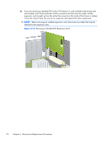
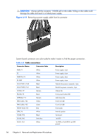
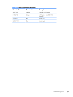
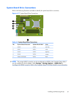
CAUTION: Always pull the connector - NEVER pull on the cable. Pulling on the cable could damage the cable and result in a failed power supply. Figure 6-14 Removing a power supply cable from its connector System board connectors are color-coded to make it easier to find the proper connection. Table 6-3 Cable connections Connector Name Connector Color Description PWR, P1 P2 PWRCPU, P3 PS STAT SATA PWR1, P160 SATA PWR2, P161 CHFAN, P9 PB/LED, P5 CHFAN2, P11 FRNT_USB1, P24 FRNT_USB2, P25 FRONT AUD, P23 SPRK, P6 COMB, P52 SATA0, P60 SATA1, P61 White White White White Black Black Maroon Black Maroon Yellow Green Blue White Black Dark blue White Power supply, 6-pin Power supply, 6-pin Power supply, 4-pin Power supply, 6-pin Optical drive power connector, 4-pin Hard drive power connector, 4-pin Chassis fan Front power button/LED 2nd chassis fan Front I/O USB Front I/O USB Front audio Internal speaker Serial port 1st HDD 1st ODD or 2nd HDD if no HDD present 56 Chapter 6 Removal and Replacement Procedures
-
 1
1 -
2
-
3
-
4
-
5
-
6
-
7
-
8
-
9
-
10
-
11
-
12
-
13
-
14
-
15
-
16
-
17
-
18
-
19
-
20
-
21
-
22
-
23
-
24
-
25
-
26
-
27
-
28
-
29
-
30
-
31
-
32
-
33
-
34
-
35
-
36
-
37
-
38
-
39
-
40
-
41
-
42
-
43
-
44
-
45
-
46
-
47
-
48
-
49
-
50
-
51
-
52
-
53
-
54
-
55
-
56
-
57
-
58
-
59
-
60
-
 61
61 -
 62
62 -
 63
63 -
 64
64 -
 65
65 -
 66
66 -
 67
67 -
 68
68 -
 69
69 -
 70
70 -
 71
71 -
72
-
73
-
74
-
75
-
76
-
77
-
78
-
79
-
80
-
81
-
82
-
83
-
84
-
85
-
86
-
87
-
88
-
89
-
90
-
91
-
92
-
93
-
94
-
95
-
96
-
97
-
98
-
99
-
100
-
101
-
102
-
103
-
104
-
105
-
106
-
107
-
108
-
109
-
110
-
111
-
112
-
113
-
114
-
115
-
116
-
117
-
118
-
119
-
120
-
121
-
122
-
123
-
124
-
125
-
126
-
127
-
128
-
129
-
130
-
131
-
132
-
133
-
134
-
135
-
136
-
137
-
138
-
139
-
140
-
141
-
142
-
143
-
144
-
145
-
146
-
147
-
148
-
149
-
150
-
151
-
152
-
153
-
154
-
155
-
156
-
157
-
158
-
159
-
160
-
161
-
162
-
163
-
164
-
165
-
166
-
167
-
168
-
169
-
170
-
171
-
172
-
173
-
174
-
175
-
176
-
177
-
178
-
179
-
180
-
181
-
182
-
183
-
184
-
185
-
186
-
187
-
188
-
189
-
190
-
191
-
192
-
193
-
194
-
195
-
196
-
197
-
198
-
199
-
200
-
201
-
202
-
203
-
204
-
205
-
206
-
207
-
208
-
209
-
210
-
211
-
212
-
213
-
214
 |
 |