Kenwood TH-D75 User Manual - Page 10
DISPLAY, Various function indicator, Indicator, Description, Frequency Display
 |
View all Kenwood TH-D75 manuals
Add to My Manuals
Save this manual to your list of manuals |
Page 10 highlights
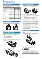
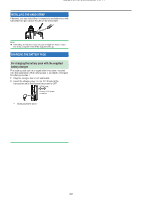
DISPLAY Common icon Display Area Frequency Display Band A Display Area Band B Display Area Various function indicator Indicator Description Performs as the S meter when receiving a signal. Displays the selected power level while transmitting. Indicates the transmission band. Appears while using Economic low output power. Appears while using Low output power. Appears while using Medium output power. Appears while using High output power. Appears while in FM mode. Page 12-7 5-3 5-2 5-3 5-3 5-3 5-3 5-2 Appears while in Narrow FM mode. 12-3 Appears while in Wide FM mode. 21-1 Appears while in AM mode. 5-2 Appears while in LSB mode. 5-2 Appears while in USB mode. 5-2 Appears while in CW mode. Appears while in Digital Repeater mode. Appears while in Digital Voice mode. Appears when Voice Alert is set to "ON". Appears when Voice Alert is set to "RX Only". Appears when the Tone function is ON. Appears when the CTCSS function is ON. Appears when the DCS function is ON. 5-2 16-1 16-1 14-24 14-24 7-2 10-1 10-2 Indicator Description Appears when the Cross tone function is "TONE/CTCSS". Appears when the Cross tone function is "DCS/CTCSS". Appears when the Cross tone function is "TONE/DCS". Appears when the Cross tone function is "DCS/OFF". Appears when the Shift function is set to plus. Appears when the Shift function is set to minus. Appears when the Shift function is set to -7.6 MHz. (TH-D75E only) Appears when the Reverse function is ON. Appears when the Attenuator function is ON. Appears when the packet communication speed in APRS mode is set to 1200 bps. Appears when the packet communication speed in APRS mode is set to 9600 bps. Appears when the packet communication speed in KISS mode is set to 1200 bps. Appears when the packet communication speed in KISS mode is set to 9600 bps. Appears while in Stand-by (Packet mode). Appears when the Beacon function is ON. Appears when the Object function is ON. Page 10-3 10-3 10-3 10-3 7-3 7-3 7-3 7-3 12-1 14-12 14-12 15-1 15-1 15-1 14-13 14-15 Appears when the built-in GPS function is ON and positioning. 13-1 Appears when the built-in GPS function is ON and not positioning. 13-1 4-3
-
 1
1 -
2
-
3
-
4
-
 5
5 -
 6
6 -
 7
7 -
 8
8 -
 9
9 -
 10
10 -
 11
11 -
 12
12 -
 13
13 -
 14
14 -
 15
15 -
16
-
17
-
18
-
19
-
20
-
21
-
22
-
23
-
24
-
25
-
26
-
27
-
28
-
29
-
30
-
31
-
32
-
33
-
34
-
35
-
36
-
37
-
38
-
39
-
40
-
41
-
42
-
43
-
44
-
45
-
46
-
47
-
48
-
49
-
50
-
51
-
52
-
53
-
54
-
55
-
56
-
57
-
58
-
59
-
60
-
61
-
62
-
63
-
64
-
65
-
66
-
67
-
68
-
69
-
70
-
71
-
72
-
73
-
74
-
75
-
76
-
77
-
78
-
79
-
80
-
81
-
82
-
83
-
84
-
85
-
86
-
87
-
88
-
89
-
90
-
91
-
92
-
93
-
94
-
95
-
96
-
97
-
98
-
99
-
100
-
101
-
102
-
103
-
104
-
105
-
106
-
107
-
108
-
109
-
110
-
111
-
112
-
113
-
114
-
115
-
116
-
117
-
118
-
119
-
120
-
121
-
122
-
123
-
124
-
125
-
126
-
127
-
128
-
129
-
130
-
131
-
132
-
133
 |
 |
