Kenwood TH-D75 User Manual - Page 79
SETTING WAY POINT, Turn time, Way Point Format, Way Point Length, Way Point Output
 |
View all Kenwood TH-D75 manuals
Add to My Manuals
Save this manual to your list of manuals |
Page 79 highlights
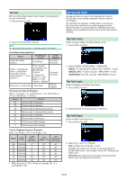
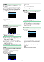
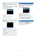
Turn time Minimum time delay between each beacon transmission by change of direction. 1 Access Menu No. 535. 2 Select from [5] to [180] seconds. @Note: ¡ Adjust the Setting values to match the actual driving status. SmartBeaconing Operation: Speed Transmission Interval Above the Under Over (Only when the set ≧ ) The interval is calculated using the following formula: (Transmission Interval = x ÷ Speed) Below the Corner Pegging Operates normally Operates normally Will not operate Transmission Interval Example: (with = 5, = 70, = 30 min, = 120 sec) Speed Interval 80 120 seconds (2 minutes) 70 120 seconds (2 minutes) 50 168 seconds (2 minutes 48 seconds) 30 280 seconds (4 minutes 40 seconds) 20 420 seconds (7 minutes) 10 840 seconds (14 minutes) 5 1680 seconds (28 minutes) 0 1800 seconds (30 minutes) Corner Pegging Operation Example: (with = 30° = 24) Speed ÷ Speed (1) (2) Turn Threshold (3)=(1)+(2) 60 24 (x10) 4° 30° 34° 50 24 (x10) 6° 30° 36° 30 24 (x10) 8° 30° 38° 20 24 (x10) 12° 30° 42° 10 24 (x10) 24° 30° 54° 5 24 (x10) 48° 30° 78° • When the value of "Turn Threshold" exceeds 120°, it is calculated as 120°. SETTING WAY POINT A waypoint refers to a point that is registered in external devices with a name being assigned to specific position coordinates. By outputting the Callsigns of other stations received by the transceiver and the position data as waypoint data, these information can be displayed on GPS receivers with display screen and tablet screens where APRS application is installed. Way Point Format Select the type of Way point Format that is sent. 1 Access Menu No. 540. 2 Select [NMEA], [MAGELLAN] or [KENWOOD]. NMEA]: The data using the NMEA 0183 "$GPWPL" format. [MAGELLAN]: The data using the " $PMGNWPL" format. [KENWOOD]: The data using the " $PKWDWPL" format. Way Point Length Select the length of the Way Point Name. 1 Access Menu No. 541. 2 Select [6-Char], [7-Char], [8-Char], or [9-Char] Way Point Output Select the Way Point output type. 1 Access Menu No. 542. 2 Select [All], [Local], or [Filtered] [All]: All Way point information is sent. [Local]: If the position limit is ON, all the data within the position limit is sent. If the position limit is OFF, all Way point data is sent. [Filtered]: Information that is permitted using the packet filter is output as Way point information. 14-18
-
 1
1 -
2
-
3
-
4
-
5
-
6
-
7
-
8
-
9
-
10
-
11
-
12
-
13
-
14
-
15
-
16
-
17
-
18
-
19
-
20
-
21
-
22
-
23
-
24
-
25
-
26
-
27
-
28
-
29
-
30
-
31
-
32
-
33
-
34
-
35
-
36
-
37
-
38
-
39
-
40
-
41
-
42
-
43
-
44
-
45
-
46
-
47
-
48
-
49
-
50
-
51
-
52
-
53
-
54
-
55
-
56
-
57
-
58
-
59
-
60
-
61
-
62
-
63
-
64
-
65
-
66
-
67
-
68
-
69
-
70
-
71
-
72
-
73
-
 74
74 -
 75
75 -
 76
76 -
 77
77 -
 78
78 -
 79
79 -
 80
80 -
 81
81 -
 82
82 -
 83
83 -
 84
84 -
85
-
86
-
87
-
88
-
89
-
90
-
91
-
92
-
93
-
94
-
95
-
96
-
97
-
98
-
99
-
100
-
101
-
102
-
103
-
104
-
105
-
106
-
107
-
108
-
109
-
110
-
111
-
112
-
113
-
114
-
115
-
116
-
117
-
118
-
119
-
120
-
121
-
122
-
123
-
124
-
125
-
126
-
127
-
128
-
129
-
130
-
131
-
132
-
133
 |
 |
