Lantronix SLC 32 Lantronix SLC - User Guide - Page 286
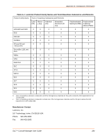
Appendix H: DC Connector Instructions, SLC™ Console Manager User Guide
 |
View all Lantronix SLC 32 manuals
Add to My Manuals
Save this manual to your list of manuals |
Page 286 highlights
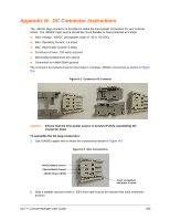
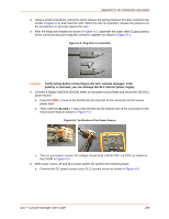
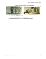
Appendix H: DC Connector Instructions 3. Using a small screwdriver, press the slot to release the spring pressure for each conductor (as shown in Figure H-2) and insert the wire. When the wire is in position, release the pressure on the screwdriver to securely capture the wire. 4. After the leads are installed as shown in Figure H-2, assemble the strain relief (2 gray pieces) to the connector plug and snap the connector together as shown in Figure H-3. Figure H-3 Plug Parts to Assemble Caution: Verify wiring before connecting to the SLC console manager. If the polarity is reversed, you can damage the SLC internal power supply. 5. Connect a Digital Volt/OHM (DVOM) meter to the power source leads and verify the (-48 VDC) power source. a. Insert the RED (+) lead of the DVOM into the top hole of the connector for the source power lead. b. Then insert the BLACK (-) lead of the DVOM into the bottom hole of the connector for the return power lead as shown in Figure H-4. Figure H-4 Verification of the Power Source c. Turn on your power source, the voltage should read (-48.00 VDC ±.5 VDC) as shown in the DVOM in Figure H-4. 6. With power source off and SLC power switch off, perform the following steps: a. Connect the DC power cords to your SLC console server as shown in Figure H-5. SLC™ Console Manager User Guide 286
-
 1
1 -
2
-
3
-
4
-
5
-
6
-
7
-
8
-
9
-
10
-
11
-
12
-
13
-
14
-
15
-
16
-
17
-
18
-
19
-
20
-
21
-
22
-
23
-
24
-
25
-
26
-
27
-
28
-
29
-
30
-
31
-
32
-
33
-
34
-
35
-
36
-
37
-
38
-
39
-
40
-
41
-
42
-
43
-
44
-
45
-
46
-
47
-
48
-
49
-
50
-
51
-
52
-
53
-
54
-
55
-
56
-
57
-
58
-
59
-
60
-
61
-
62
-
63
-
64
-
65
-
66
-
67
-
68
-
69
-
70
-
71
-
72
-
73
-
74
-
75
-
76
-
77
-
78
-
79
-
80
-
81
-
82
-
83
-
84
-
85
-
86
-
87
-
88
-
89
-
90
-
91
-
92
-
93
-
94
-
95
-
96
-
97
-
98
-
99
-
100
-
101
-
102
-
103
-
104
-
105
-
106
-
107
-
108
-
109
-
110
-
111
-
112
-
113
-
114
-
115
-
116
-
117
-
118
-
119
-
120
-
121
-
122
-
123
-
124
-
125
-
126
-
127
-
128
-
129
-
130
-
131
-
132
-
133
-
134
-
135
-
136
-
137
-
138
-
139
-
140
-
141
-
142
-
143
-
144
-
145
-
146
-
147
-
148
-
149
-
150
-
151
-
152
-
153
-
154
-
155
-
156
-
157
-
158
-
159
-
160
-
161
-
162
-
163
-
164
-
165
-
166
-
167
-
168
-
169
-
170
-
171
-
172
-
173
-
174
-
175
-
176
-
177
-
178
-
179
-
180
-
181
-
182
-
183
-
184
-
185
-
186
-
187
-
188
-
189
-
190
-
191
-
192
-
193
-
194
-
195
-
196
-
197
-
198
-
199
-
200
-
201
-
202
-
203
-
204
-
205
-
206
-
207
-
208
-
209
-
210
-
211
-
212
-
213
-
214
-
215
-
216
-
217
-
218
-
219
-
220
-
221
-
222
-
223
-
224
-
225
-
226
-
227
-
228
-
229
-
230
-
231
-
232
-
233
-
234
-
235
-
236
-
237
-
238
-
239
-
240
-
241
-
242
-
243
-
244
-
245
-
246
-
247
-
248
-
249
-
250
-
251
-
252
-
253
-
254
-
255
-
256
-
257
-
258
-
259
-
260
-
261
-
262
-
263
-
264
-
265
-
266
-
267
-
268
-
269
-
270
-
271
-
272
-
273
-
274
-
275
-
276
-
277
-
278
-
279
-
280
-
 281
281 -
 282
282 -
 283
283 -
 284
284 -
 285
285 -
 286
286 -
 287
287 -
 288
288 -
 289
289 -
 290
290 -
 291
291 -
292
-
293
-
294
-
295
-
296
-
297
-
298
-
299
 |
 |
