Lenovo NetVista Hardware Maintenence Manual for Netvista 6838 and 6848 systems - Page 47
FRU information (service only), Types 6838 and 6848 removals, System board layout
 |
View all Lenovo NetVista manuals
Add to My Manuals
Save this manual to your list of manuals |
Page 47 highlights
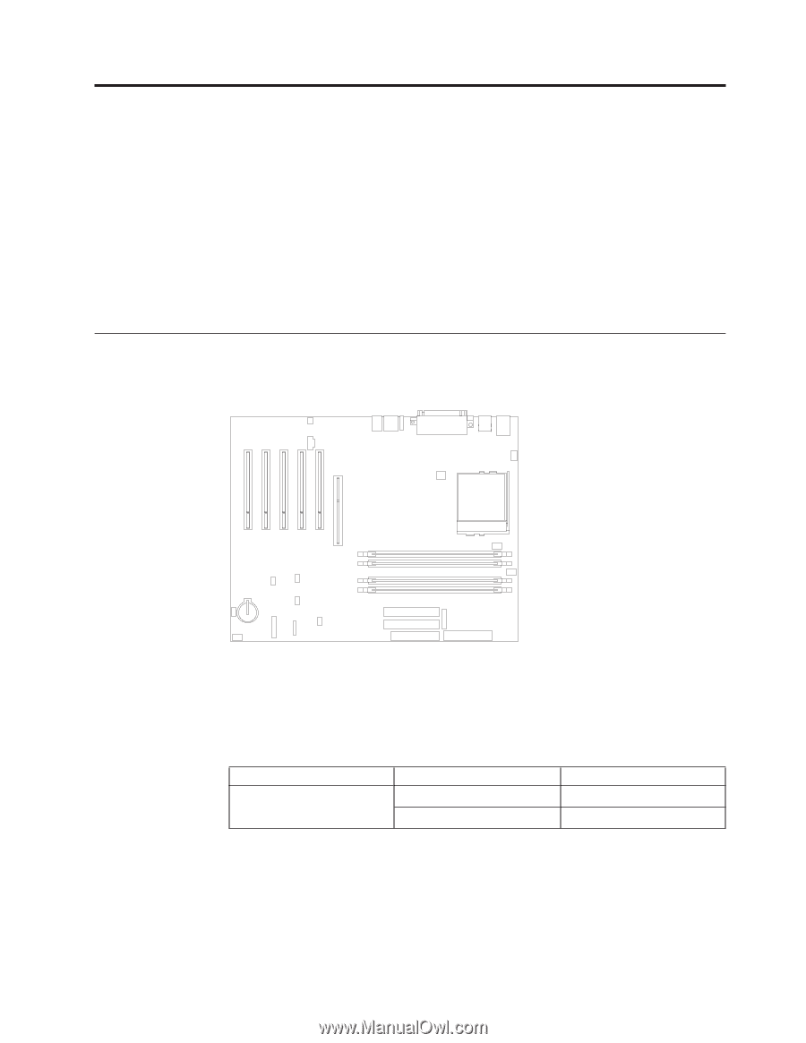
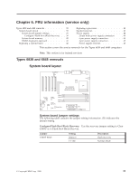
Chapter 6. FRU information (service only) Types 6838 and 6848 removals 39 System board layout 39 System board jumper settings 39 Configure/Flash Boot Block Recovery . . 39 System board memory 40 RIMM diagnostic approach 42 Replacing a system board 42 Replacing a processor 43 Speaker removal 43 Power supply 44 20-pin main power supply connection . . . 44 6-pin power supply connection 45 4-pin power supply connection 45 Power supply removal 46 This section covers the service removals for the Types 6838 and 6848 computers. Note: This section is for trained servicers Types 6838 and 6848 removals System board layout Speaker CD Audio PCI PCI PCI PCI PCI AGP Connector Power Your computer may not have all connectors shown. Fan 4 CPU Recovery Jumper Backup Battery Front Panel Fan 1 Wake on LAN Alert on LAN RIMM 1 RIMM 2 RIMM 3 RIMM 4 USB Tamper Alert Fan 3 Fan 2 Secondary IDE Primary IDE FDD Connector Power Power SCSI LED System board jumper settings The following table contains the jumper setting information. (D) indicates the default setting. Configure/Flash Boot Block Recovery: Use the recovery jumper setting to Clear CMOS or to Flash Boot Block Recover. Jumper CMOS Reset Setting Remove 1-2 (D) Description Flash recovery Normal Mode © Copyright IBM Corp. 2000 39
-
 1
1 -
2
-
3
-
4
-
5
-
6
-
7
-
8
-
9
-
10
-
11
-
12
-
13
-
14
-
15
-
16
-
17
-
18
-
19
-
20
-
21
-
22
-
23
-
24
-
25
-
26
-
27
-
28
-
29
-
30
-
31
-
32
-
33
-
34
-
35
-
36
-
37
-
38
-
39
-
40
-
41
-
 42
42 -
 43
43 -
 44
44 -
 45
45 -
 46
46 -
 47
47 -
 48
48 -
 49
49 -
 50
50 -
 51
51 -
 52
52 -
53
-
54
-
55
-
56
-
57
-
58
-
59
-
60
-
61
-
62
-
63
-
64
-
65
-
66
-
67
-
68
-
69
-
70
-
71
-
72
-
73
-
74
-
75
-
76
-
77
-
78
-
79
-
80
-
81
-
82
-
83
-
84
-
85
-
86
-
87
-
88
-
89
-
90
-
91
-
92
-
93
-
94
-
95
-
96
-
97
-
98
-
99
-
100
-
101
-
102
-
103
-
104
-
105
-
106
-
107
-
108
-
109
-
110
-
111
-
112
-
113
-
114
-
115
-
116
-
117
-
118
-
119
-
120
-
121
-
122
-
123
-
124
-
125
-
126
-
127
-
128
-
129
-
130
 |
 |