Lexmark X464de Service Manual - Page 20
Preface, Change history - maintenance kit for
 |
View all Lexmark X464de manuals
Add to My Manuals
Save this manual to your list of manuals |
Page 20 highlights
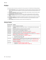
7014-xxx Preface This manual contains maintenance procedures for service personnel. It is divided into the following chapters: 1. General information contains a general description of the printer and the maintenance approach used to repair it. Special tools and test equipment, as well as general environmental and safety instructions, are discussed. 2. Diagnostic information contains an error indicator table, symptom tables, and service checks used to isolate failing field replaceable units (FRUs). 3. Diagnostic aids contains tests and checks used to locate or repeat symptoms of printer problems. 4. Repair information provides instructions for making printer adjustments and removing and installing FRUs. 5. Connector locations uses illustrations to identify the connector locations and test points on the printer. 6. Preventive maintenance contains the lubrication specifications and recommendations to prevent problems. 7. Parts catalog contains illustrations and part numbers for individual FRUs. Change history Revision date 2013/11/11 2013/07/16 2013/07/01 2012/09/24 2012/09/19 2012/07/10 2012/05/02 2012/02/08 2011/10/28 2011/9/14 2011/07/28 Updates Deleted all instances of 40X5057. Updated the Media ACM ASM feeder removal-The media feed clutch should only be loosened. Replaced 40X5836 with 40x5743 (Assembly 2: Imaging). Deleted reference to wiring diagram on page 5-6. Changed ADF separator pad PN from 40X5472 to 40X8419. Updated the description for the "80 Routine Maintenance" on page 2-18. Replaced all references to 40X5471 to 40X7545 for the ADF separator roll in "Imaging" on page 7-5 and in "Maintenance kits" on page 6-1. Added the following part numbers in "Imaging" on page 7-5: • 40X7546 for the ADF hinge, right • 40X7547 for the ADF hinge, left Added this warning: "Warning: Do not strip the insulation off the red and black wires. The connectors will not work if the insulation is removed," in step 8 of "Media feed clutch removal" on page 4-50. Revised the media feed clutch assembly removal procedure in "Media feed clutch removal" on page 4-50. • Updated the "Printhead removal" on page 4-74. • Updated the "Scanner assembly removal" on page 4-91. -xx Service Manual
-
 1
1 -
2
-
3
-
4
-
5
-
6
-
7
-
8
-
9
-
10
-
11
-
12
-
13
-
14
-
 15
15 -
 16
16 -
 17
17 -
 18
18 -
 19
19 -
 20
20 -
 21
21 -
 22
22 -
 23
23 -
 24
24 -
 25
25 -
26
-
27
-
28
-
29
-
30
-
31
-
32
-
33
-
34
-
35
-
36
-
37
-
38
-
39
-
40
-
41
-
42
-
43
-
44
-
45
-
46
-
47
-
48
-
49
-
50
-
51
-
52
-
53
-
54
-
55
-
56
-
57
-
58
-
59
-
60
-
61
-
62
-
63
-
64
-
65
-
66
-
67
-
68
-
69
-
70
-
71
-
72
-
73
-
74
-
75
-
76
-
77
-
78
-
79
-
80
-
81
-
82
-
83
-
84
-
85
-
86
-
87
-
88
-
89
-
90
-
91
-
92
-
93
-
94
-
95
-
96
-
97
-
98
-
99
-
100
-
101
-
102
-
103
-
104
-
105
-
106
-
107
-
108
-
109
-
110
-
111
-
112
-
113
-
114
-
115
-
116
-
117
-
118
-
119
-
120
-
121
-
122
-
123
-
124
-
125
-
126
-
127
-
128
-
129
-
130
-
131
-
132
-
133
-
134
-
135
-
136
-
137
-
138
-
139
-
140
-
141
-
142
-
143
-
144
-
145
-
146
-
147
-
148
-
149
-
150
-
151
-
152
-
153
-
154
-
155
-
156
-
157
-
158
-
159
-
160
-
161
-
162
-
163
-
164
-
165
-
166
-
167
-
168
-
169
-
170
-
171
-
172
-
173
-
174
-
175
-
176
-
177
-
178
-
179
-
180
-
181
-
182
-
183
-
184
-
185
-
186
-
187
-
188
-
189
-
190
-
191
-
192
-
193
-
194
-
195
-
196
-
197
-
198
-
199
-
200
-
201
-
202
-
203
-
204
-
205
-
206
-
207
-
208
-
209
-
210
-
211
-
212
-
213
-
214
-
215
-
216
-
217
-
218
-
219
-
220
-
221
-
222
-
223
-
224
-
225
-
226
-
227
-
228
-
229
-
230
-
231
-
232
-
233
-
234
-
235
-
236
-
237
-
238
-
239
-
240
-
241
-
242
-
243
-
244
-
245
-
246
-
247
-
248
-
249
-
250
-
251
-
252
-
253
-
254
-
255
-
256
-
257
-
258
-
259
-
260
-
261
-
262
-
263
-
264
-
265
-
266
-
267
-
268
-
269
-
270
-
271
-
272
-
273
-
274
-
275
-
276
-
277
-
278
-
279
-
280
-
281
-
282
-
283
-
284
-
285
-
286
-
287
-
288
-
289
-
290
-
291
-
292
-
293
-
294
-
295
-
296
-
297
-
298
-
299
-
300
-
301
-
302
-
303
-
304
-
305
-
306
-
307
-
308
-
309
-
310
 |
 |