Lexmark X464de Service Manual - Page 98
ADF paper jam service check, ADF feed errors service check, Replace the ADF unit. See
 |
View all Lexmark X464de manuals
Add to My Manuals
Save this manual to your list of manuals |
Page 98 highlights
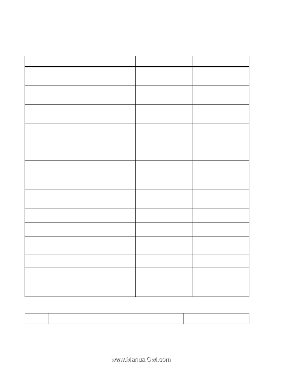
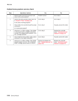
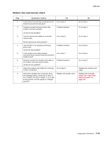
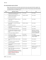
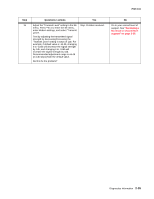
7014-xxx ADF paper jam service check Note: This service check should be used if the paper feeds and jams in the ADF. If the paper is not feeding into the ADF see "ADF feed errors service check" on page 2-60. Step 1 2 3 4 6 7 8 9 10 11 11 Questions / actions Yes No If the ADF is multi-feeding, check for dirt on the ADF separator pad and ADF separator rollers. Are they dirty? If the paper is skewing when it is fed into the ADF, check the paper guide width. Is it set correctly? If paper is skewing when fed or jamming check to see if the top cover is open or ajar. Is the ADF top cover open or ajar? Is paper failing to feed into the ADF? Perform the ADF paper present, scan 1st and scan 2nd sensor tests. Go to "Scanner Tests" on page 3-34. Clean them with a lint free cloth and isopropyl alcohol. Go to step 3. Properly close the top cover. Go to step 5. Go to step 6 Replace the separator pad and ADF pick roll. Set the paper guides so they contact the edges of the paper. If the paper is jamming in the ADF, go to step 6 There is no issue. Go to step 9. Are the sensors working properly. Check the leading edge of the paper to ensure the paper is not curled or bent in a way that would keep it from contacting the paper present sensor actuator. Is the paper damaged? Is there dirt in the sensors, or is the paper present actuator stuck? Bad media. Clean the sensors, or remove debris from the actuators. Go to step 7. Go to step 8. Are the sensor actuators on the ADF mechanism cover damaged? Is the ADF connector properly connected to J17 on the system board? Inspect the connections on the ADF relay card in the ADF. Are all the connections properly connected? Check the ADF cable for continuity. Is there continuity? Check for signals or voltages from J17 on the controller board. Pin 11 and 12 should measure +24VDC. Pin 14 should measure +5VDC. Are there signals or voltages present? Replace the ADF. Go to step 10. Go to step 11. Go to step 11. Replace the ADF unit. See "ADF unit removal" on page 4-88. Go to step 9. Properly connect the cable to the system board. Secure all the connections. Replace the ADF cable. Replace the controller board. See "Controller board removal" on page 4-8. ADF feed errors service check Step Questions / actions Yes No 2-60 Service Manual
-
 1
1 -
2
-
3
-
4
-
5
-
6
-
7
-
8
-
9
-
10
-
11
-
12
-
13
-
14
-
15
-
16
-
17
-
18
-
19
-
20
-
21
-
22
-
23
-
24
-
25
-
26
-
27
-
28
-
29
-
30
-
31
-
32
-
33
-
34
-
35
-
36
-
37
-
38
-
39
-
40
-
41
-
42
-
43
-
44
-
45
-
46
-
47
-
48
-
49
-
50
-
51
-
52
-
53
-
54
-
55
-
56
-
57
-
58
-
59
-
60
-
61
-
62
-
63
-
64
-
65
-
66
-
67
-
68
-
69
-
70
-
71
-
72
-
73
-
74
-
75
-
76
-
77
-
78
-
79
-
80
-
81
-
82
-
83
-
84
-
85
-
86
-
87
-
88
-
89
-
90
-
91
-
92
-
 93
93 -
 94
94 -
 95
95 -
 96
96 -
 97
97 -
 98
98 -
 99
99 -
 100
100 -
 101
101 -
 102
102 -
 103
103 -
104
-
105
-
106
-
107
-
108
-
109
-
110
-
111
-
112
-
113
-
114
-
115
-
116
-
117
-
118
-
119
-
120
-
121
-
122
-
123
-
124
-
125
-
126
-
127
-
128
-
129
-
130
-
131
-
132
-
133
-
134
-
135
-
136
-
137
-
138
-
139
-
140
-
141
-
142
-
143
-
144
-
145
-
146
-
147
-
148
-
149
-
150
-
151
-
152
-
153
-
154
-
155
-
156
-
157
-
158
-
159
-
160
-
161
-
162
-
163
-
164
-
165
-
166
-
167
-
168
-
169
-
170
-
171
-
172
-
173
-
174
-
175
-
176
-
177
-
178
-
179
-
180
-
181
-
182
-
183
-
184
-
185
-
186
-
187
-
188
-
189
-
190
-
191
-
192
-
193
-
194
-
195
-
196
-
197
-
198
-
199
-
200
-
201
-
202
-
203
-
204
-
205
-
206
-
207
-
208
-
209
-
210
-
211
-
212
-
213
-
214
-
215
-
216
-
217
-
218
-
219
-
220
-
221
-
222
-
223
-
224
-
225
-
226
-
227
-
228
-
229
-
230
-
231
-
232
-
233
-
234
-
235
-
236
-
237
-
238
-
239
-
240
-
241
-
242
-
243
-
244
-
245
-
246
-
247
-
248
-
249
-
250
-
251
-
252
-
253
-
254
-
255
-
256
-
257
-
258
-
259
-
260
-
261
-
262
-
263
-
264
-
265
-
266
-
267
-
268
-
269
-
270
-
271
-
272
-
273
-
274
-
275
-
276
-
277
-
278
-
279
-
280
-
281
-
282
-
283
-
284
-
285
-
286
-
287
-
288
-
289
-
290
-
291
-
292
-
293
-
294
-
295
-
296
-
297
-
298
-
299
-
300
-
301
-
302
-
303
-
304
-
305
-
306
-
307
-
308
-
309
-
310
 |
 |