Lexmark X464de Service Manual - Page 81
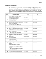
Operator panel service check, Paper feed service checks, Paper jam error indication during POST
 |
View all Lexmark X464de manuals
Add to My Manuals
Save this manual to your list of manuals |
Page 81 highlights
7014-xxx Operator panel service check Inspect the operator panel cable for damage. Make sure the cable is plugged in securely. Run POST, and check each light for proper operation. See "Power-On Self Test (POST) sequence" on page 2-1. Touch screen operator panel service check FRU Operator panel Display Operator panel keyboard Controller board Warning: Do not replace the engine board and controller board at the same time. Each board contains the printer settings. When either of these boards is new, it obtains the settings from the other board. Settings are lost when both are new and replaced at the same time. Action Touchscreen display If the touchscreen display does not come on or indicator LED on the keyboard doesn't illuminate, then open the controller board cage and locate the operator panel connector at J34. Make sure the cable is properly connected to the controller board and the controller board has input voltage to it. With the printer on, verify the following on connector J34: • Pins 1, 3, 5, and 6: 3.3 v • Pin 10, 16, 17, and 18: 5 v • Pins 2, 9, and 15: GND If any are incorrect, then see "Controller board service check" on page 2-35. If these are approximately correct and the operator panel is not functioning: 1. Turn the printer off. 2. Remove the left and right covers, 3. Tilt the operator panel keyoboard and verify the UICC cable is properly connected to the keyboard at connector J10. 4. If the cable is properly connected at both ends, check the cable for continuity. If the cable fails, replace the UICC cable. 5. Reconnect the UICC cable, and verify the display ribbone cables are properly connected to J3 and J12 on the keyboard. 6. Restart the printer. If the eight LEDs on the bottom of the keyboard card illuminate, but the display fails to illuminate, replace the touchscreen display. 7. If the eight LEDs fail to illuminate, replace the keyboard. Button keypad If the touchscreen is ok, POR into Diagnostic mode, and perform the Button test under the Hardware tests. If the buttons do not respond, then replace the keyboard . Paper feed service checks Paper jam error indication during POST FRU Fuser (exit sensor) Input/duplex sensor Manual feed sensor Action If the exit sensor flag, which is visible at the back of the fuser, is in any position other than vertical, then the printer will display a paper jam. Make sure the flag is operating freely. Replace the fuser if the sensor is damaged. Make sure the input paper feed sensors are working properly. A stuck or incorrectly installed sensor causes a paper jam indication. Diagnostics information 2-43
-
 1
1 -
2
-
3
-
4
-
5
-
6
-
7
-
8
-
9
-
10
-
11
-
12
-
13
-
14
-
15
-
16
-
17
-
18
-
19
-
20
-
21
-
22
-
23
-
24
-
25
-
26
-
27
-
28
-
29
-
30
-
31
-
32
-
33
-
34
-
35
-
36
-
37
-
38
-
39
-
40
-
41
-
42
-
43
-
44
-
45
-
46
-
47
-
48
-
49
-
50
-
51
-
52
-
53
-
54
-
55
-
56
-
57
-
58
-
59
-
60
-
61
-
62
-
63
-
64
-
65
-
66
-
67
-
68
-
69
-
70
-
71
-
72
-
73
-
74
-
75
-
 76
76 -
 77
77 -
 78
78 -
 79
79 -
 80
80 -
 81
81 -
 82
82 -
 83
83 -
 84
84 -
 85
85 -
 86
86 -
87
-
88
-
89
-
90
-
91
-
92
-
93
-
94
-
95
-
96
-
97
-
98
-
99
-
100
-
101
-
102
-
103
-
104
-
105
-
106
-
107
-
108
-
109
-
110
-
111
-
112
-
113
-
114
-
115
-
116
-
117
-
118
-
119
-
120
-
121
-
122
-
123
-
124
-
125
-
126
-
127
-
128
-
129
-
130
-
131
-
132
-
133
-
134
-
135
-
136
-
137
-
138
-
139
-
140
-
141
-
142
-
143
-
144
-
145
-
146
-
147
-
148
-
149
-
150
-
151
-
152
-
153
-
154
-
155
-
156
-
157
-
158
-
159
-
160
-
161
-
162
-
163
-
164
-
165
-
166
-
167
-
168
-
169
-
170
-
171
-
172
-
173
-
174
-
175
-
176
-
177
-
178
-
179
-
180
-
181
-
182
-
183
-
184
-
185
-
186
-
187
-
188
-
189
-
190
-
191
-
192
-
193
-
194
-
195
-
196
-
197
-
198
-
199
-
200
-
201
-
202
-
203
-
204
-
205
-
206
-
207
-
208
-
209
-
210
-
211
-
212
-
213
-
214
-
215
-
216
-
217
-
218
-
219
-
220
-
221
-
222
-
223
-
224
-
225
-
226
-
227
-
228
-
229
-
230
-
231
-
232
-
233
-
234
-
235
-
236
-
237
-
238
-
239
-
240
-
241
-
242
-
243
-
244
-
245
-
246
-
247
-
248
-
249
-
250
-
251
-
252
-
253
-
254
-
255
-
256
-
257
-
258
-
259
-
260
-
261
-
262
-
263
-
264
-
265
-
266
-
267
-
268
-
269
-
270
-
271
-
272
-
273
-
274
-
275
-
276
-
277
-
278
-
279
-
280
-
281
-
282
-
283
-
284
-
285
-
286
-
287
-
288
-
289
-
290
-
291
-
292
-
293
-
294
-
295
-
296
-
297
-
298
-
299
-
300
-
301
-
302
-
303
-
304
-
305
-
306
-
307
-
308
-
309
-
310
 |
 |
