Lexmark X464de Service Manual - Page 75
Cooling fan service check, Cover interlock switch service check, Engine board, removal
 |
View all Lexmark X464de manuals
Add to My Manuals
Save this manual to your list of manuals |
Page 75 highlights
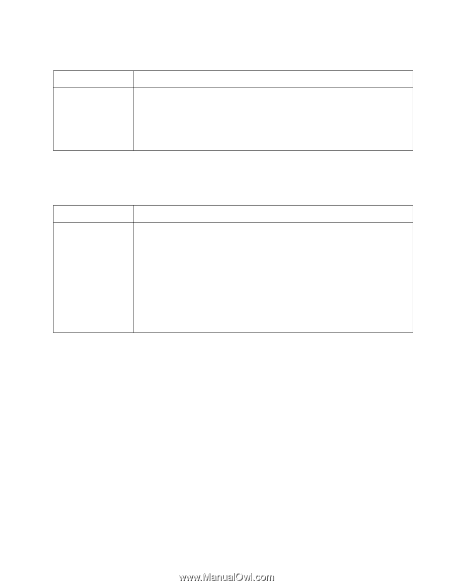
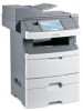
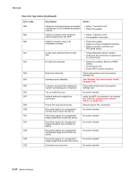
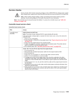
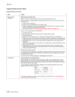
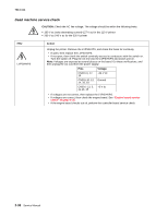
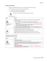
7014-xxx Cooling fan service check FRU Cooling fan Action Make sure the fan cable plug is properly seated at J36 (engine board). Turn the printer on. Within a few seconds, the engine board assembly should apply +24 V dc to pin 2. • If voltage is not present, then check or replace the engine board. See "Engine board removal" on page 2-15. • If voltage is present, then check pin 1 for 24 V dc as well. If it is close to 24 V dc while the fan is still idle, then replace the fan. See "Fan removal" on page 2-24. Cover interlock switch service check Note: Make sure a print cartridge assembly is installed and the cover closes all the way, engaging the cover open switch lever. FRU Cover interlock switch Action Disconnect the cover interlock cable from the controller board at J11. With the printer turned off: 1. Verify continuity between cable pin 1 and pin 2 with the door closed and discontinuity with the door open. 2. Verify continuity between cable pin 1 and pin 3 with the door open and discontinuity with the door closed. 3. Verify discontinuity between cable pins 2 and 3 whether the door is open or closed. • If any fail, then replace the cover interlock switch. • If both pass continuity, then turn the printer on, and measure +5 V dc on pin 2 at J11 on the controller board. • Verify pin 3 at J6 is ground. • If voltage or ground is not present, then see "Engine board service check" on page 2-36 for more information. Diagnostics information 2-37
-
 1
1 -
2
-
3
-
4
-
5
-
6
-
7
-
8
-
9
-
10
-
11
-
12
-
13
-
14
-
15
-
16
-
17
-
18
-
19
-
20
-
21
-
22
-
23
-
24
-
25
-
26
-
27
-
28
-
29
-
30
-
31
-
32
-
33
-
34
-
35
-
36
-
37
-
38
-
39
-
40
-
41
-
42
-
43
-
44
-
45
-
46
-
47
-
48
-
49
-
50
-
51
-
52
-
53
-
54
-
55
-
56
-
57
-
58
-
59
-
60
-
61
-
62
-
63
-
64
-
65
-
66
-
67
-
68
-
69
-
 70
70 -
 71
71 -
 72
72 -
 73
73 -
 74
74 -
 75
75 -
 76
76 -
 77
77 -
 78
78 -
 79
79 -
 80
80 -
81
-
82
-
83
-
84
-
85
-
86
-
87
-
88
-
89
-
90
-
91
-
92
-
93
-
94
-
95
-
96
-
97
-
98
-
99
-
100
-
101
-
102
-
103
-
104
-
105
-
106
-
107
-
108
-
109
-
110
-
111
-
112
-
113
-
114
-
115
-
116
-
117
-
118
-
119
-
120
-
121
-
122
-
123
-
124
-
125
-
126
-
127
-
128
-
129
-
130
-
131
-
132
-
133
-
134
-
135
-
136
-
137
-
138
-
139
-
140
-
141
-
142
-
143
-
144
-
145
-
146
-
147
-
148
-
149
-
150
-
151
-
152
-
153
-
154
-
155
-
156
-
157
-
158
-
159
-
160
-
161
-
162
-
163
-
164
-
165
-
166
-
167
-
168
-
169
-
170
-
171
-
172
-
173
-
174
-
175
-
176
-
177
-
178
-
179
-
180
-
181
-
182
-
183
-
184
-
185
-
186
-
187
-
188
-
189
-
190
-
191
-
192
-
193
-
194
-
195
-
196
-
197
-
198
-
199
-
200
-
201
-
202
-
203
-
204
-
205
-
206
-
207
-
208
-
209
-
210
-
211
-
212
-
213
-
214
-
215
-
216
-
217
-
218
-
219
-
220
-
221
-
222
-
223
-
224
-
225
-
226
-
227
-
228
-
229
-
230
-
231
-
232
-
233
-
234
-
235
-
236
-
237
-
238
-
239
-
240
-
241
-
242
-
243
-
244
-
245
-
246
-
247
-
248
-
249
-
250
-
251
-
252
-
253
-
254
-
255
-
256
-
257
-
258
-
259
-
260
-
261
-
262
-
263
-
264
-
265
-
266
-
267
-
268
-
269
-
270
-
271
-
272
-
273
-
274
-
275
-
276
-
277
-
278
-
279
-
280
-
281
-
282
-
283
-
284
-
285
-
286
-
287
-
288
-
289
-
290
-
291
-
292
-
293
-
294
-
295
-
296
-
297
-
298
-
299
-
300
-
301
-
302
-
303
-
304
-
305
-
306
-
307
-
308
-
309
-
310
 |
 |