Lexmark X464de Service Manual - Page 264
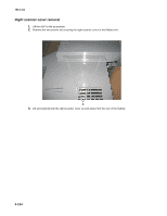
ADF cable removal, Left scanner cover removal on Controller board shield
 |
View all Lexmark X464de manuals
Add to My Manuals
Save this manual to your list of manuals |
Page 264 highlights
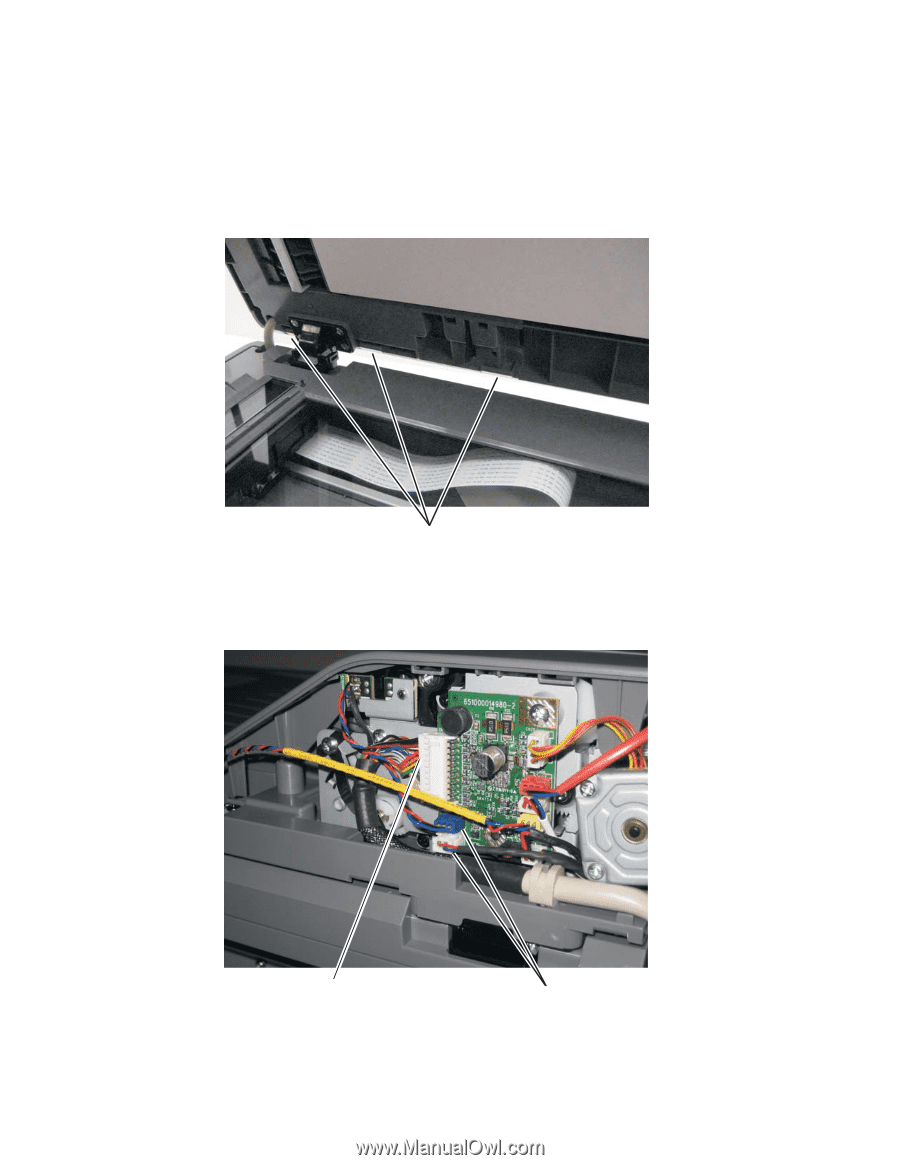
7014-xxx ADF cable removal 1. Remove the left scanner cover. See "Left scanner cover removal" on page 4-103. 2. Remove the left cover. See "Left side cover removal" on page 4-33. 3. Remove the controller board shield. See "Controller board shield" on page 4-11. 4. Lift the flatbed cover and unsnap the three tabs (A) securing the ADF rear cover to the ADF. A 5. Remove the rear ADF cover. 6. Disconnect the ADF cable (B) and two sensor connections (C) on the relay card above the ADF relay cable. B CCB 7. Disconnect the ADF cable from connector J17 on the controller board. 8. Disconnect the ADF cable ground from the controller cage. 4-102
-
 1
1 -
2
-
3
-
4
-
5
-
6
-
7
-
8
-
9
-
10
-
11
-
12
-
13
-
14
-
15
-
16
-
17
-
18
-
19
-
20
-
21
-
22
-
23
-
24
-
25
-
26
-
27
-
28
-
29
-
30
-
31
-
32
-
33
-
34
-
35
-
36
-
37
-
38
-
39
-
40
-
41
-
42
-
43
-
44
-
45
-
46
-
47
-
48
-
49
-
50
-
51
-
52
-
53
-
54
-
55
-
56
-
57
-
58
-
59
-
60
-
61
-
62
-
63
-
64
-
65
-
66
-
67
-
68
-
69
-
70
-
71
-
72
-
73
-
74
-
75
-
76
-
77
-
78
-
79
-
80
-
81
-
82
-
83
-
84
-
85
-
86
-
87
-
88
-
89
-
90
-
91
-
92
-
93
-
94
-
95
-
96
-
97
-
98
-
99
-
100
-
101
-
102
-
103
-
104
-
105
-
106
-
107
-
108
-
109
-
110
-
111
-
112
-
113
-
114
-
115
-
116
-
117
-
118
-
119
-
120
-
121
-
122
-
123
-
124
-
125
-
126
-
127
-
128
-
129
-
130
-
131
-
132
-
133
-
134
-
135
-
136
-
137
-
138
-
139
-
140
-
141
-
142
-
143
-
144
-
145
-
146
-
147
-
148
-
149
-
150
-
151
-
152
-
153
-
154
-
155
-
156
-
157
-
158
-
159
-
160
-
161
-
162
-
163
-
164
-
165
-
166
-
167
-
168
-
169
-
170
-
171
-
172
-
173
-
174
-
175
-
176
-
177
-
178
-
179
-
180
-
181
-
182
-
183
-
184
-
185
-
186
-
187
-
188
-
189
-
190
-
191
-
192
-
193
-
194
-
195
-
196
-
197
-
198
-
199
-
200
-
201
-
202
-
203
-
204
-
205
-
206
-
207
-
208
-
209
-
210
-
211
-
212
-
213
-
214
-
215
-
216
-
217
-
218
-
219
-
220
-
221
-
222
-
223
-
224
-
225
-
226
-
227
-
228
-
229
-
230
-
231
-
232
-
233
-
234
-
235
-
236
-
237
-
238
-
239
-
240
-
241
-
242
-
243
-
244
-
245
-
246
-
247
-
248
-
249
-
250
-
251
-
252
-
253
-
254
-
255
-
256
-
257
-
258
-
 259
259 -
 260
260 -
 261
261 -
 262
262 -
 263
263 -
 264
264 -
 265
265 -
 266
266 -
 267
267 -
 268
268 -
 269
269 -
270
-
271
-
272
-
273
-
274
-
275
-
276
-
277
-
278
-
279
-
280
-
281
-
282
-
283
-
284
-
285
-
286
-
287
-
288
-
289
-
290
-
291
-
292
-
293
-
294
-
295
-
296
-
297
-
298
-
299
-
300
-
301
-
302
-
303
-
304
-
305
-
306
-
307
-
308
-
309
-
310
 |
 |
4-102
7014-xxx
ADF cable removal
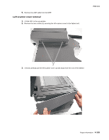
1.
Remove the left scanner cover. See
“Left scanner cover removal” on page 4-103
.
2.
Remove the left cover. See
“Left side cover removal” on page 4-33
.
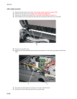
3.
Remove the controller board shield. See
“Controller board shield” on page 4-11
.
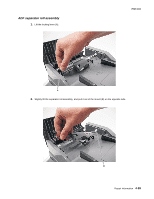
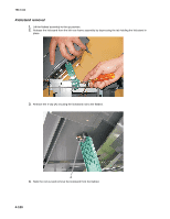
4.
Lift the flatbed cover and unsnap the three tabs (A) securing the ADF rear cover to the ADF.
5.
Remove the rear ADF cover.
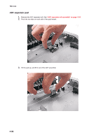
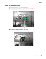
6.
Disconnect the ADF cable (B) and two sensor connections (C) on the relay card above the ADF relay
cable.
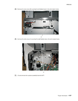
7.
Disconnect the ADF cable from connector J17 on the controller board.
8.
Disconnect the ADF cable ground from the controller cage.
A
B
C