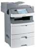
Lexmark X464de Service Manual - Page 234
Tub assembly removal
 |
View all Lexmark X464de manuals
Add to My Manuals
Save this manual to your list of manuals |
Page 234 highlights
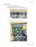
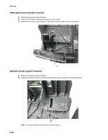
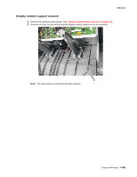
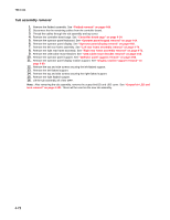
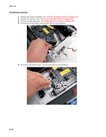
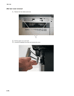
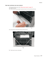
7014-xxx Tub assembly removal 1. Remove the flatbed assembly. See "Flatbed removal" on page 4-89. 2. Disconnect the the remaining cables from the controller board. 3. Thread the cables through the tub assembly and top cover. 4. Remove the controller board cage. See "Controller board cage" on page 4-14. 5. Remove the operator panel keyboard. See "Operator panel keypad removal" on page 4-64. 6. Remove the operator panel display. See "Operator panel display removal" on page 4-65. 7. Remove the left rear frame assembly. See "Left rear frame assembly removal" on page 4-70. 8. Remove the right rear frame assembly. See "Right rear frame assembly removal" on page 4-71. 9. Remove the USB cable mount bracket. See "USB cable mount bracket removal" on page 4-68. 10. Remove the operator panel support. See "Operator panel support removal" on page 4-68. 11. Remove the operator panel display rotation support. See "Display rotation support removal" on page 4-69. 12. Remove the top and side screws securing the left flatbed support. 13. Remove the left flatbed support. 14. Remove the top and side screws securing the right flatbed support. 15. Remove the right flatbed support. 16. Lift the tub assembly off of the MFP. Note: After removing the tub assembly, remove the output binLED and LED cover. See "Output bin LED and lens removal" on page 4-101. These will be used on the new tub assembly. 4-72
-
 1
1 -
2
-
3
-
4
-
5
-
6
-
7
-
8
-
9
-
10
-
11
-
12
-
13
-
14
-
15
-
16
-
17
-
18
-
19
-
20
-
21
-
22
-
23
-
24
-
25
-
26
-
27
-
28
-
29
-
30
-
31
-
32
-
33
-
34
-
35
-
36
-
37
-
38
-
39
-
40
-
41
-
42
-
43
-
44
-
45
-
46
-
47
-
48
-
49
-
50
-
51
-
52
-
53
-
54
-
55
-
56
-
57
-
58
-
59
-
60
-
61
-
62
-
63
-
64
-
65
-
66
-
67
-
68
-
69
-
70
-
71
-
72
-
73
-
74
-
75
-
76
-
77
-
78
-
79
-
80
-
81
-
82
-
83
-
84
-
85
-
86
-
87
-
88
-
89
-
90
-
91
-
92
-
93
-
94
-
95
-
96
-
97
-
98
-
99
-
100
-
101
-
102
-
103
-
104
-
105
-
106
-
107
-
108
-
109
-
110
-
111
-
112
-
113
-
114
-
115
-
116
-
117
-
118
-
119
-
120
-
121
-
122
-
123
-
124
-
125
-
126
-
127
-
128
-
129
-
130
-
131
-
132
-
133
-
134
-
135
-
136
-
137
-
138
-
139
-
140
-
141
-
142
-
143
-
144
-
145
-
146
-
147
-
148
-
149
-
150
-
151
-
152
-
153
-
154
-
155
-
156
-
157
-
158
-
159
-
160
-
161
-
162
-
163
-
164
-
165
-
166
-
167
-
168
-
169
-
170
-
171
-
172
-
173
-
174
-
175
-
176
-
177
-
178
-
179
-
180
-
181
-
182
-
183
-
184
-
185
-
186
-
187
-
188
-
189
-
190
-
191
-
192
-
193
-
194
-
195
-
196
-
197
-
198
-
199
-
200
-
201
-
202
-
203
-
204
-
205
-
206
-
207
-
208
-
209
-
210
-
211
-
212
-
213
-
214
-
215
-
216
-
217
-
218
-
219
-
220
-
221
-
222
-
223
-
224
-
225
-
226
-
227
-
228
-
 229
229 -
 230
230 -
 231
231 -
 232
232 -
 233
233 -
 234
234 -
 235
235 -
 236
236 -
 237
237 -
 238
238 -
 239
239 -
240
-
241
-
242
-
243
-
244
-
245
-
246
-
247
-
248
-
249
-
250
-
251
-
252
-
253
-
254
-
255
-
256
-
257
-
258
-
259
-
260
-
261
-
262
-
263
-
264
-
265
-
266
-
267
-
268
-
269
-
270
-
271
-
272
-
273
-
274
-
275
-
276
-
277
-
278
-
279
-
280
-
281
-
282
-
283
-
284
-
285
-
286
-
287
-
288
-
289
-
290
-
291
-
292
-
293
-
294
-
295
-
296
-
297
-
298
-
299
-
300
-
301
-
302
-
303
-
304
-
305
-
306
-
307
-
308
-
309
-
310
 |
 |