Lexmark X464de Service Manual - Page 61
removal on Printhead service
 |
View all Lexmark X464de manuals
Add to My Manuals
Save this manual to your list of manuals |
Page 61 highlights
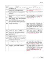
7014-xxx Error Description Action 201.02 Exit sensor never made by leading edge of page. Also Remove the PC kit and paper or debris at the input known as internal jam. sensor. 201.03 Video never started on the page at the input sensor within two inches after hitting the input sensor Check the printhead. See "Printhead service check" on page 2-54. 201.05 Restart attempted after an internal jam without the cover open/close event. It is likely that the jam was never cleared. Check the paper path and remove any media in the path. 201.25 201.26 Exit sensor never made by leading edge of media when feeding out the media that was detected during warm-up. Page at fuser nip before fuser started ramping toward desired temperature. Indicates code may be receiving more interrupts than intended Remove the toner cartridge/PC kit and check for obstructions between the input sensor and the fuser. if the media continues to stop at the entrance or in the fuser, then replace the fuser. See "Fuser removal" on page 4-28. 201.27 Page at fuser nip before fuser reached acceptable operating temperature. Page arrived at fuser earlier than expected, so it was probably staged prematurely. 202.00 Paper jam around exit sensor. 202.01 Exit sensor never broke on the trailing edge of the sheet at the exit sensor. 202.02 Exit sensor never broke from sheet ahead of page heading toward the exit sensor. Open the rear cover and look for obstructions in the path way. If there are none, then inspect for damage at the fuser, rear door, exit guide, and top cover. Often, the leading edge of the media will indicate the vacinity of damage. If damage is found, then replace the damaged part. Note: Print a page with the rear door open to isolate the fuser from the other parts. Open the rear door, and inspect the flag on the exit sensor. The flag is located behind the fuser exit rollers, about mid printer. If the flag does not rotate freely or has no spring action, then replace the fuser. See "Fuser removal" on page 4-28. 202.06 Exit sensor bounced 202.13 Exit sensor covered, media not expected (media not in machine during warm-up) 202.25 Exit sensor never broke from the sheet ahead of the page heading toward the exit sensor when feeding out the media detected during warm-up. 202.26 Trailing edge never cleared exit sensor when feeding out media that was detected during warm-up. Open the rear door, and inspect the flag on the exit sensor. The flag is located behind the fuser exit rollers, about mid printer. If the flag does not rotate freely or has no spring action, then replace the fuser. See "Fuser removal" on page 4-28. 202.32 Long media or shingled multi feed stopped before sending to duplex. Check the paper setting and correct if needed. While feeding along the media, and immediately after it enters the output bin, open the reat door and obscure the trailing edge and the sensor flag. If there is slippage in the exit guide, then replace the exit guide. See Go to "Rear exit guide assembly with sensor and reversing solenoid removal" on page 4-78. Diagnostics information 2-23
-
 1
1 -
2
-
3
-
4
-
5
-
6
-
7
-
8
-
9
-
10
-
11
-
12
-
13
-
14
-
15
-
16
-
17
-
18
-
19
-
20
-
21
-
22
-
23
-
24
-
25
-
26
-
27
-
28
-
29
-
30
-
31
-
32
-
33
-
34
-
35
-
36
-
37
-
38
-
39
-
40
-
41
-
42
-
43
-
44
-
45
-
46
-
47
-
48
-
49
-
50
-
51
-
52
-
53
-
54
-
55
-
 56
56 -
 57
57 -
 58
58 -
 59
59 -
 60
60 -
 61
61 -
 62
62 -
 63
63 -
 64
64 -
 65
65 -
 66
66 -
67
-
68
-
69
-
70
-
71
-
72
-
73
-
74
-
75
-
76
-
77
-
78
-
79
-
80
-
81
-
82
-
83
-
84
-
85
-
86
-
87
-
88
-
89
-
90
-
91
-
92
-
93
-
94
-
95
-
96
-
97
-
98
-
99
-
100
-
101
-
102
-
103
-
104
-
105
-
106
-
107
-
108
-
109
-
110
-
111
-
112
-
113
-
114
-
115
-
116
-
117
-
118
-
119
-
120
-
121
-
122
-
123
-
124
-
125
-
126
-
127
-
128
-
129
-
130
-
131
-
132
-
133
-
134
-
135
-
136
-
137
-
138
-
139
-
140
-
141
-
142
-
143
-
144
-
145
-
146
-
147
-
148
-
149
-
150
-
151
-
152
-
153
-
154
-
155
-
156
-
157
-
158
-
159
-
160
-
161
-
162
-
163
-
164
-
165
-
166
-
167
-
168
-
169
-
170
-
171
-
172
-
173
-
174
-
175
-
176
-
177
-
178
-
179
-
180
-
181
-
182
-
183
-
184
-
185
-
186
-
187
-
188
-
189
-
190
-
191
-
192
-
193
-
194
-
195
-
196
-
197
-
198
-
199
-
200
-
201
-
202
-
203
-
204
-
205
-
206
-
207
-
208
-
209
-
210
-
211
-
212
-
213
-
214
-
215
-
216
-
217
-
218
-
219
-
220
-
221
-
222
-
223
-
224
-
225
-
226
-
227
-
228
-
229
-
230
-
231
-
232
-
233
-
234
-
235
-
236
-
237
-
238
-
239
-
240
-
241
-
242
-
243
-
244
-
245
-
246
-
247
-
248
-
249
-
250
-
251
-
252
-
253
-
254
-
255
-
256
-
257
-
258
-
259
-
260
-
261
-
262
-
263
-
264
-
265
-
266
-
267
-
268
-
269
-
270
-
271
-
272
-
273
-
274
-
275
-
276
-
277
-
278
-
279
-
280
-
281
-
282
-
283
-
284
-
285
-
286
-
287
-
288
-
289
-
290
-
291
-
292
-
293
-
294
-
295
-
296
-
297
-
298
-
299
-
300
-
301
-
302
-
303
-
304
-
305
-
306
-
307
-
308
-
309
-
310
 |
 |
