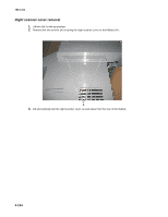
Lexmark X464de Service Manual - Page 268
Installing an Internal Solutions Port (ISP)
 |
View all Lexmark X464de manuals
Add to My Manuals
Save this manual to your list of manuals |
Page 268 highlights
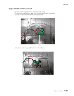
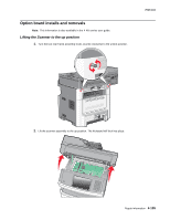
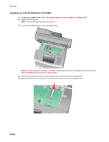
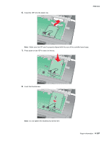
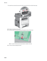
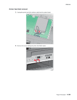
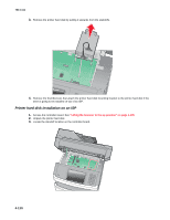
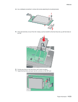
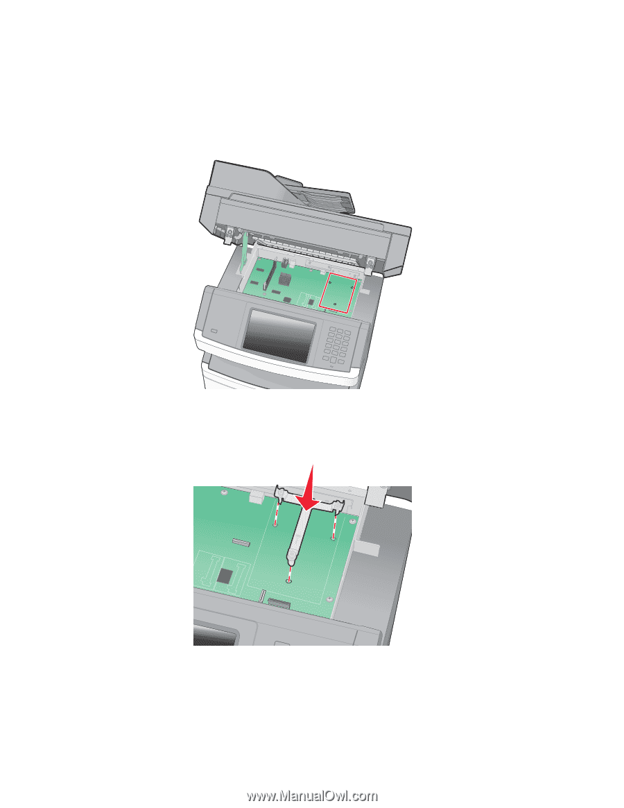
7014-xxx Installing an Internal Solutions Port (ISP) 1. Access the controller board. See "Lifting the Scanner to the up position" on page 4-105. 2. Unpack the ISP and tee. Note: Avoid touching components on the card. 3. Locate the standoff location on the controller board. Note: If an optional printer hard disk is currently installed, then the printer hard disk must first be removed. See "Printer hard disk removal" on page 4-109. 4. Remove the metal cover from the ISP opening in the rear of the controller board cage. 5. Align the posts of the mounting tee, and press down to secure it to the controller board. 4-106
-
 1
1 -
2
-
3
-
4
-
5
-
6
-
7
-
8
-
9
-
10
-
11
-
12
-
13
-
14
-
15
-
16
-
17
-
18
-
19
-
20
-
21
-
22
-
23
-
24
-
25
-
26
-
27
-
28
-
29
-
30
-
31
-
32
-
33
-
34
-
35
-
36
-
37
-
38
-
39
-
40
-
41
-
42
-
43
-
44
-
45
-
46
-
47
-
48
-
49
-
50
-
51
-
52
-
53
-
54
-
55
-
56
-
57
-
58
-
59
-
60
-
61
-
62
-
63
-
64
-
65
-
66
-
67
-
68
-
69
-
70
-
71
-
72
-
73
-
74
-
75
-
76
-
77
-
78
-
79
-
80
-
81
-
82
-
83
-
84
-
85
-
86
-
87
-
88
-
89
-
90
-
91
-
92
-
93
-
94
-
95
-
96
-
97
-
98
-
99
-
100
-
101
-
102
-
103
-
104
-
105
-
106
-
107
-
108
-
109
-
110
-
111
-
112
-
113
-
114
-
115
-
116
-
117
-
118
-
119
-
120
-
121
-
122
-
123
-
124
-
125
-
126
-
127
-
128
-
129
-
130
-
131
-
132
-
133
-
134
-
135
-
136
-
137
-
138
-
139
-
140
-
141
-
142
-
143
-
144
-
145
-
146
-
147
-
148
-
149
-
150
-
151
-
152
-
153
-
154
-
155
-
156
-
157
-
158
-
159
-
160
-
161
-
162
-
163
-
164
-
165
-
166
-
167
-
168
-
169
-
170
-
171
-
172
-
173
-
174
-
175
-
176
-
177
-
178
-
179
-
180
-
181
-
182
-
183
-
184
-
185
-
186
-
187
-
188
-
189
-
190
-
191
-
192
-
193
-
194
-
195
-
196
-
197
-
198
-
199
-
200
-
201
-
202
-
203
-
204
-
205
-
206
-
207
-
208
-
209
-
210
-
211
-
212
-
213
-
214
-
215
-
216
-
217
-
218
-
219
-
220
-
221
-
222
-
223
-
224
-
225
-
226
-
227
-
228
-
229
-
230
-
231
-
232
-
233
-
234
-
235
-
236
-
237
-
238
-
239
-
240
-
241
-
242
-
243
-
244
-
245
-
246
-
247
-
248
-
249
-
250
-
251
-
252
-
253
-
254
-
255
-
256
-
257
-
258
-
259
-
260
-
261
-
262
-
 263
263 -
 264
264 -
 265
265 -
 266
266 -
 267
267 -
 268
268 -
 269
269 -
 270
270 -
 271
271 -
 272
272 -
 273
273 -
274
-
275
-
276
-
277
-
278
-
279
-
280
-
281
-
282
-
283
-
284
-
285
-
286
-
287
-
288
-
289
-
290
-
291
-
292
-
293
-
294
-
295
-
296
-
297
-
298
-
299
-
300
-
301
-
302
-
303
-
304
-
305
-
306
-
307
-
308
-
309
-
310
 |
 |
4-106
7014-xxx
Installing an Internal Solutions Port (ISP)
1.
Access the controller board. See
“Lifting the Scanner to the up position” on page 4-105
.
2.
Unpack the ISP and tee.
Note:
Avoid touching components on the card.
3.
Locate the standoff location on the controller board.
Note:
If an optional printer hard disk is currently installed, then the printer hard disk must first be removed.
See
“Printer hard disk removal” on page 4-109
.
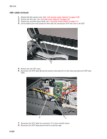
4.
Remove the metal cover from the ISP opening in the rear of the controller board cage.
5.
Align the posts of the mounting tee, and press down to secure it to the controller board.