Lexmark X464de Service Manual - Page 284
Lexmark X46x controller and engine board connector pin values, Operator panel UICC - Controller Board
 |
View all Lexmark X464de manuals
Add to My Manuals
Save this manual to your list of manuals |
Page 284 highlights
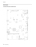
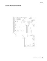
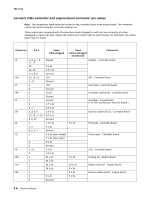
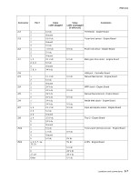
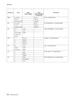
7014-xxx Lexmark X46x controller and engine board connector pin values Note: The connections listed below are located on the controller board or the engine board. The comments column lists which board the connection appears on. These values were measured with all connections made (plugged) or with only one connector at a time unplugged to expose the pins. Always disconnect and connect with the printer power off. Otherwise, the values below may not match. Connector Pin # J8 1, 3, 5, 7, 9, 11, 14 10 12, 13 2, 4, 6, 8 J16 10, 12, 14 1, 4 7 J7 1 4 J99 3 1 J4 1 2 3, 4 J34 1, 3, 5, 6 10, 16 ,17, 18 2, 9, 15 J6 1 2, 3 4, 5, 6, 7 J11 1 2 3 J9 1, 10 9 J36 1 2 J10 1 2 J35 1 2 3 Value cable plugged Signals 5 V dc 3.3 V dc Ground +5V Ground +5V Ground +3.3V Ground Ground 1.7 V dc 3.3 V dc 3.3 V dc 5.0 V dc Ground > 0 V dc 5 V dc Ground 5 V dc (door closed) 0 V dc (door open) 5 V dc Ground 5 V dc 2.9 V dc 24 V dc 24 V dc 24 V dc 24 V dc 5 V dc Ground Value cable unplugged (if different) Comments Modem - Controller Board 5 V dc ISP - Controller Board Cave light - Controller board Controller cooling fan - Controller board Cartridge - Engine Board (The front access door must be closed.) Operator panel (UICC) - Controller Board Printhead - Controller Board Cover open - Controller Board 0 V dc 24 V dc 0 V dc 5 V dc 5 V dc LSU - Controller Board Cooling fan - Engine Board Duplex solenoid - Engine Board Narrow media sensor - Engine Board 5-6 Service Manual
-
 1
1 -
2
-
3
-
4
-
5
-
6
-
7
-
8
-
9
-
10
-
11
-
12
-
13
-
14
-
15
-
16
-
17
-
18
-
19
-
20
-
21
-
22
-
23
-
24
-
25
-
26
-
27
-
28
-
29
-
30
-
31
-
32
-
33
-
34
-
35
-
36
-
37
-
38
-
39
-
40
-
41
-
42
-
43
-
44
-
45
-
46
-
47
-
48
-
49
-
50
-
51
-
52
-
53
-
54
-
55
-
56
-
57
-
58
-
59
-
60
-
61
-
62
-
63
-
64
-
65
-
66
-
67
-
68
-
69
-
70
-
71
-
72
-
73
-
74
-
75
-
76
-
77
-
78
-
79
-
80
-
81
-
82
-
83
-
84
-
85
-
86
-
87
-
88
-
89
-
90
-
91
-
92
-
93
-
94
-
95
-
96
-
97
-
98
-
99
-
100
-
101
-
102
-
103
-
104
-
105
-
106
-
107
-
108
-
109
-
110
-
111
-
112
-
113
-
114
-
115
-
116
-
117
-
118
-
119
-
120
-
121
-
122
-
123
-
124
-
125
-
126
-
127
-
128
-
129
-
130
-
131
-
132
-
133
-
134
-
135
-
136
-
137
-
138
-
139
-
140
-
141
-
142
-
143
-
144
-
145
-
146
-
147
-
148
-
149
-
150
-
151
-
152
-
153
-
154
-
155
-
156
-
157
-
158
-
159
-
160
-
161
-
162
-
163
-
164
-
165
-
166
-
167
-
168
-
169
-
170
-
171
-
172
-
173
-
174
-
175
-
176
-
177
-
178
-
179
-
180
-
181
-
182
-
183
-
184
-
185
-
186
-
187
-
188
-
189
-
190
-
191
-
192
-
193
-
194
-
195
-
196
-
197
-
198
-
199
-
200
-
201
-
202
-
203
-
204
-
205
-
206
-
207
-
208
-
209
-
210
-
211
-
212
-
213
-
214
-
215
-
216
-
217
-
218
-
219
-
220
-
221
-
222
-
223
-
224
-
225
-
226
-
227
-
228
-
229
-
230
-
231
-
232
-
233
-
234
-
235
-
236
-
237
-
238
-
239
-
240
-
241
-
242
-
243
-
244
-
245
-
246
-
247
-
248
-
249
-
250
-
251
-
252
-
253
-
254
-
255
-
256
-
257
-
258
-
259
-
260
-
261
-
262
-
263
-
264
-
265
-
266
-
267
-
268
-
269
-
270
-
271
-
272
-
273
-
274
-
275
-
276
-
277
-
278
-
 279
279 -
 280
280 -
 281
281 -
 282
282 -
 283
283 -
 284
284 -
 285
285 -
 286
286 -
 287
287 -
 288
288 -
 289
289 -
290
-
291
-
292
-
293
-
294
-
295
-
296
-
297
-
298
-
299
-
300
-
301
-
302
-
303
-
304
-
305
-
306
-
307
-
308
-
309
-
310
 |
 |
