Lexmark X464de Service Manual - Page 73
Service checks, Controller board service check
 |
View all Lexmark X464de manuals
Add to My Manuals
Save this manual to your list of manuals |
Page 73 highlights
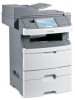
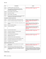
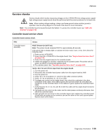
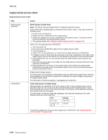
7014-xxx Service checks Service checks which involve measuring voltages on the LVPS/HVPS (low voltage power supply/ high voltage power supply board) should be performed with the printer positioned on its back side. Note: When making voltage readings, always use frame ground unless another ground is specified. See the wiring diagram in the back of the book for more information. Note: The controller board is located beneath the flatbed. To access the controller board, see "ADF unit removal" on page 4-88. Controller board service check Controller board service check FRU Action Controller board assembly POST (Power-On Self Test) Note: The printer should complete POST in approximately 45 seconds. If the printer fails to display lights or activate the drive motor, fuser, or fan, then check the following order: 1. Power to the LVPS/HVPS. 2. Power from the LVPS/HVPS to the engine board. See "Engine board service check" on page 2-36. 3. Power from the engine board to the controller board. 4. Cables are plugged in correctly, especially for the operator panel. The printer will not power-up without a functioning operator panel. 5. The operator panel. See "Operator panel service check" on page 2-43. Verify +24 V dc and +5V dc input from the engine board. 1. Turn the printer off. 2. Disconnect the controller board power cable from the engine board at J503. 3. Turn the printer on. 4. Verify +24 V dc on positions 17, and 19 of the cable connector (J503). 5. Verify +5 V dc on positions 11, 13, 15 on J503. 6. If voltages are correct on the engine board, then check the continuity in the other conductors of the cable. If the cable is good, then turn the printer off, and check the connectors on the controller board. If the cable isn't good, replace the cantroller board cable. 7. Verify that pins 10, 12, 14, 16, and 18 on both the cable and the engine board connector are grounded. 8. If grounds are not correct on the cable, but the cable passes continuity otherwise, then check the controller board. 9. If the grounds are not correct on the controller board, then replace the controller board. (Check with one probe on the connector pin and the other on the card's ground plane found at each screw head.) Diagnostics information 2-35
-
 1
1 -
2
-
3
-
4
-
5
-
6
-
7
-
8
-
9
-
10
-
11
-
12
-
13
-
14
-
15
-
16
-
17
-
18
-
19
-
20
-
21
-
22
-
23
-
24
-
25
-
26
-
27
-
28
-
29
-
30
-
31
-
32
-
33
-
34
-
35
-
36
-
37
-
38
-
39
-
40
-
41
-
42
-
43
-
44
-
45
-
46
-
47
-
48
-
49
-
50
-
51
-
52
-
53
-
54
-
55
-
56
-
57
-
58
-
59
-
60
-
61
-
62
-
63
-
64
-
65
-
66
-
67
-
 68
68 -
 69
69 -
 70
70 -
 71
71 -
 72
72 -
 73
73 -
 74
74 -
 75
75 -
 76
76 -
 77
77 -
 78
78 -
79
-
80
-
81
-
82
-
83
-
84
-
85
-
86
-
87
-
88
-
89
-
90
-
91
-
92
-
93
-
94
-
95
-
96
-
97
-
98
-
99
-
100
-
101
-
102
-
103
-
104
-
105
-
106
-
107
-
108
-
109
-
110
-
111
-
112
-
113
-
114
-
115
-
116
-
117
-
118
-
119
-
120
-
121
-
122
-
123
-
124
-
125
-
126
-
127
-
128
-
129
-
130
-
131
-
132
-
133
-
134
-
135
-
136
-
137
-
138
-
139
-
140
-
141
-
142
-
143
-
144
-
145
-
146
-
147
-
148
-
149
-
150
-
151
-
152
-
153
-
154
-
155
-
156
-
157
-
158
-
159
-
160
-
161
-
162
-
163
-
164
-
165
-
166
-
167
-
168
-
169
-
170
-
171
-
172
-
173
-
174
-
175
-
176
-
177
-
178
-
179
-
180
-
181
-
182
-
183
-
184
-
185
-
186
-
187
-
188
-
189
-
190
-
191
-
192
-
193
-
194
-
195
-
196
-
197
-
198
-
199
-
200
-
201
-
202
-
203
-
204
-
205
-
206
-
207
-
208
-
209
-
210
-
211
-
212
-
213
-
214
-
215
-
216
-
217
-
218
-
219
-
220
-
221
-
222
-
223
-
224
-
225
-
226
-
227
-
228
-
229
-
230
-
231
-
232
-
233
-
234
-
235
-
236
-
237
-
238
-
239
-
240
-
241
-
242
-
243
-
244
-
245
-
246
-
247
-
248
-
249
-
250
-
251
-
252
-
253
-
254
-
255
-
256
-
257
-
258
-
259
-
260
-
261
-
262
-
263
-
264
-
265
-
266
-
267
-
268
-
269
-
270
-
271
-
272
-
273
-
274
-
275
-
276
-
277
-
278
-
279
-
280
-
281
-
282
-
283
-
284
-
285
-
286
-
287
-
288
-
289
-
290
-
291
-
292
-
293
-
294
-
295
-
296
-
297
-
298
-
299
-
300
-
301
-
302
-
303
-
304
-
305
-
306
-
307
-
308
-
309
-
310
 |
 |