Pioneer SC-35 Owner's Manual - Page 31
Connecting your TV with no HDMI input
 |
UPC - 884938108751
View all Pioneer SC-35 manuals
Add to My Manuals
Save this manual to your list of manuals |
Page 31 highlights
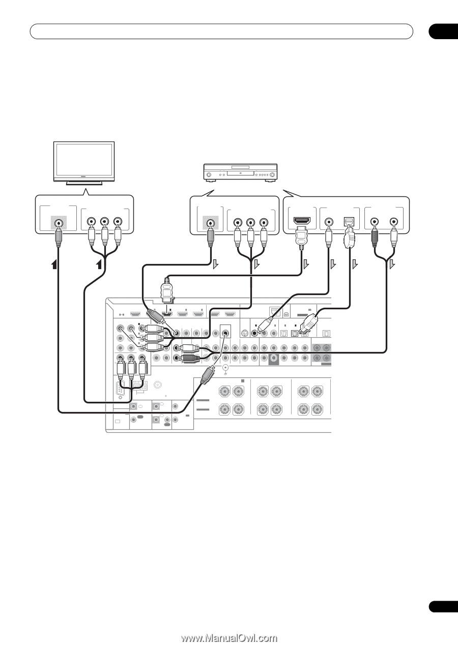
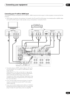
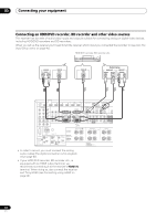
Connecting your equipment 03 Connecting your TV with no HDMI input This diagram shows connections of a TV (with no HDMI input) and DVD player (or other playback component) to the receiver. • With these connections, the picture is not output to the TV even if the DVD player is connected with an HDMI cable. Connect the DVD player's video signals using a composite or component cord. TV VIDEO IN VIDEO Select one COMPONENT VIDEO IN PR PB Y DVD player, etc. VIDEO OUT VIDEO Select one COMPONENT VIDEO OUT PR PB Y HDMI OUT Select one DIGITAL OUT COAXIAL OPTICAL AUDIO OUT R ANALOG L HDMI BD IN IN 1 IN 2 IN 3 IN 4 OUT 1 (CONTROL) OUT 2 LAN (10/100) ASSIGNABLE 14 XM ADAPTER PORT IN (OUTPUT 5 V 100 mA MAX) COMPONENT VIDEO ASSIGNABLE IN 1 (DVD) SIRIUS COAXIAL ASSIGNABLE OPTICAL ASSIGNABLE MONITOR OUT IN IN 1 IN 2 IN 3 IN 1 IN 2 IN 3 (DVD) (CD) (CD-R) (TV/SAT) (DVR/BDR) (VIDEO) OUT IN 2 (DVR/BDR) VIDEO IN 3 (VIDEO) ZONE2 ZONE3 OUT OUT DVD TV/SAT VIDEO IN IN IN DVR/BDR OUT IN PHONO CD IN IN CD-R/TAPE OUT IN FRONT CENTER SURROUND SURR BACK FH/FW (Single) FRONT CENTER S MONITOR OUT ZONE 2 OUT Y PB PR ANTENNA RS-232C (OUTPUT 5 V 150 mA MAX) CU-RF100 AM LOOP FM UNBAL 75 CONTROL IN IN 1 IR IN 2 OUT OUT SPEAKERS Class 2 Wiring SIGNAL GND FRONT HEIGHT/WIDE/ B R L SUBWOOFER PRE OUT SUBWOOFER SURROUND BACK SURROUND R L (Single) R L 12 V 1 TRIGGER (OUTPUT 12 V 2 TOTAL 150 mA MAX) SELECTABLE SEE INSTRUCTION MANUAL SELECTABLE VOIR LE MODE D'EMPLOI CAUTION: SPEAKER IMPEDANCE 6 Ω - 16 Ω . ATTENTION: ENCEINTE D'IMPEDANCE DE 6 Ω - 16 Ω . • Connect using an HDMI cable to listen to HD audio on the receiver. Do not use an HDMI cable to input video signals. Depending on the video component, it may not be possible to output signals connected by HDMI and other methods simultaneously, and it may be necessary to make output settings. Please refer to the operating instructions supplied with your component for more information. • If you want to listen to the sound of the TV over the receiver, connect the receiver and TV with audio cables (page 29). • If you use an optical digital audio cable, you'll need to tell the receiver which digital input you connected the player to (see The Input Setup menu on page 45). 31 En
-
 1
1 -
2
-
3
-
4
-
5
-
6
-
7
-
8
-
9
-
10
-
11
-
12
-
13
-
14
-
15
-
16
-
17
-
18
-
19
-
20
-
21
-
22
-
23
-
24
-
25
-
 26
26 -
 27
27 -
 28
28 -
 29
29 -
 30
30 -
 31
31 -
 32
32 -
 33
33 -
 34
34 -
 35
35 -
 36
36 -
37
-
38
-
39
-
40
-
41
-
42
-
43
-
44
-
45
-
46
-
47
-
48
-
49
-
50
-
51
-
52
-
53
-
54
-
55
-
56
-
57
-
58
-
59
-
60
-
61
-
62
-
63
-
64
-
65
-
66
-
67
-
68
-
69
-
70
-
71
-
72
-
73
-
74
-
75
-
76
-
77
-
78
-
79
-
80
-
81
-
82
-
83
-
84
-
85
-
86
-
87
-
88
-
89
-
90
-
91
-
92
-
93
-
94
-
95
-
96
-
97
-
98
-
99
-
100
-
101
-
102
-
103
-
104
-
105
-
106
-
107
-
108
-
109
-
110
-
111
-
112
-
113
-
114
-
115
-
116
-
117
-
118
-
119
-
120
-
121
-
122
-
123
-
124
-
125
-
126
-
127
-
128
-
129
-
130
-
131
-
132
-
133
-
134
-
135
-
136
-
137
-
138
-
139
-
140
-
141
-
142
-
143
-
144
-
145
-
146
-
147
-
148
 |
 |