Pioneer SC-35 Owner's Manual - Page 38
Connecting to the network through LAN interface, AUDIO ZONE 3 - service manual
 |
UPC - 884938108751
View all Pioneer SC-35 manuals
Add to My Manuals
Save this manual to your list of manuals |
Page 38 highlights
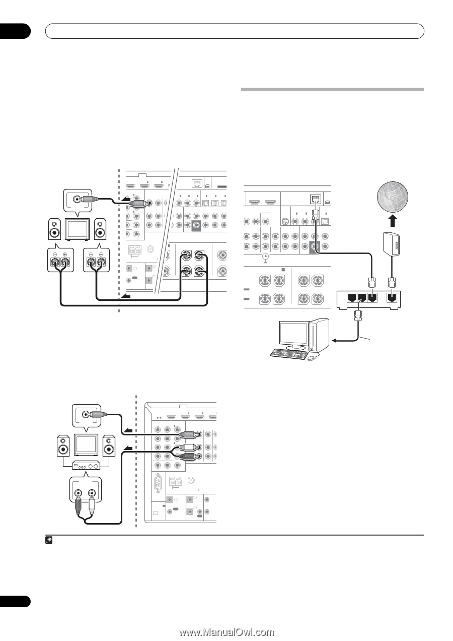
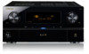
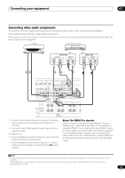
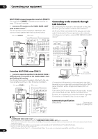
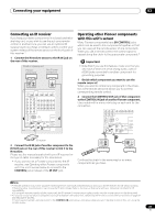
03 Connecting your equipment MULTI-ZONE setup using speaker terminals (ZONE 2) You must select ZONE 2 in Speaker system setting on page 115 to use this setup. • Connect a TV monitor to the VIDEO ZONE 2 OUT jacks on this receiver.1 You should have a pair of speakers attached to the surround back speaker terminals as shown below. Sub zone (ZONE 2) Main zone VIDEO IN L R BD IN OUINT 2 LAN (10/100) IN 1 2 XM ADAPTER P IN (OUTPUT 5 V 100 mA MAX) ENT VIDEO NABLE IN 1 (DVD) IN 2 (DVR/BDR) SIRIUS COAXIAL ASSIGNABLE OPTICAL ASSIGNABLE IN IN 1 IN 2 IN 3 IN 1 IN 2 IN 3 (DVD) (CD) (CD-R) (TV/SAT) (DVR/BDR) (VIDEO) DEO IN 3 (VIDEO) ZONE2 OUT ZONE3CD DVD CD-R/TAPE OUT IN IN OUT IN FRONT CENTER SURROUND SURR BACK FH/FW (Single) MONITOR OUT ZONE 2 OUT PB PR ANTENNA L HT/WIDE/ B L SUBWOOFER PRE OU SURROUND BACK SU R L (Single) R AM LOOP FM UNBAL 75 CONTROL IN IN 1 IR IN 2 OUT OUT 1 1T ( 1 2 T 1 CAUTION: SPEAKER IMPEDANCE 6 Ω - 16 Ω . ATTENTION: ENCEINTE D'IMPEDANCE DE 6 Ω - 16 Ω . Secondary MULTI-ZONE setup (ZONE 3) • Connect a separate amplifier to the AUDIO ZONE 3 OUT jacks and a TV monitor to the VIDEO ZONE 3 OUT jack, both on this receiver. You should have a pair of speakers attached to the sub zone amplifier as shown in the following illustration. Sub zone (ZONE 3) Main zone VIDEO IN AUDIO IN R L HDMI BD IN IN 1 IN 2 IN 3 ASSIGNABLE 14 COMPONENT VIDEO ASSIGNABLE IN 1 (DVD) IN 2 (DVR/BDR) IN 3 (VIDEO) ZONE2 ZONE3 OUT OUT DVD TV/ IN I MONITOR OUT ZONE 2 OUT Y PB PR ANTENNA RS-232C (OUTPUT 5 V 150 mA MAX) CU-RF100 AM LOOP FM UNBAL 75 CONTROL IN IN 1 IR IN 2 OUT OUT 12 V 1 TRIG (OUT 12 V 2 TOTA 150 m Connecting to the network through LAN interface By connecting this receiver to the network via the LAN terminal, you can listen to Internet radio stations.2 SC-37 only: When connected in this way, you can play audio files stored on the components on the network, including your computer, using HOME MEDIA GALLERY inputs.3 OUT 1 (CONTROL) OUT 2 LAN (10/100) XM IN SIRIUS COAXIAL ASSIGNABLE OPTICAL MONITOR OUT IN IN 1 IN 2 IN 3 IN 1 (DVD) (CD) (CD-R) (TV/SAT) VIDEO DVR/BDR OUT IN PHONO CD IN IN CD-R/TAPE OUT IN FRONT CENTER SURROUND Internet Modem KERS Wiring SIGNAL GND FRONT HEIGHT/WIDE/ B R L SUBWOOFER SURROUND BACK R L (Single TABLE TRUCTION L TABLE MODE OI LAN 3 2 1 WAN Router to LAN port LAN cable (sold separately) PC Connect the LAN terminal on this receiver to the LAN terminal on your router (with or without the built-in DHCP server function) with a straight LAN cable (CAT 5 or higher). Turn on the DHCP server function of your router. In case your router does not have the built-in DHCP server function, it is necessary to set up the network manually. For details, see Network Setup menu on page 117. LAN terminal specifications LAN terminal Ethernet jack 10BASE-T/100BASE-TX Note 1 • COMPONENT VIDEO ZONE 2 OUT can be used to output clear images. • The GUI screen is not displayed if only the COMPONENT VIDEO ZONE 2 OUT jack is connected. • The video convert function does not work for ZONE 2. Connect the composite video and component video to the same types of jacks for the inputs and outputs. 2 To listen to Internet radio stations, you must sign a contract with an ISP (Internet Service Provider) beforehand. 3 • Photo or video files cannot be played back. • With Windows Media Player 11 or Windows Media Player 12, you can even play back copyrighted audio files on this receiver. 38 En
-
 1
1 -
2
-
3
-
4
-
5
-
6
-
7
-
8
-
9
-
10
-
11
-
12
-
13
-
14
-
15
-
16
-
17
-
18
-
19
-
20
-
21
-
22
-
23
-
24
-
25
-
26
-
27
-
28
-
29
-
30
-
31
-
32
-
 33
33 -
 34
34 -
 35
35 -
 36
36 -
 37
37 -
 38
38 -
 39
39 -
 40
40 -
 41
41 -
 42
42 -
 43
43 -
44
-
45
-
46
-
47
-
48
-
49
-
50
-
51
-
52
-
53
-
54
-
55
-
56
-
57
-
58
-
59
-
60
-
61
-
62
-
63
-
64
-
65
-
66
-
67
-
68
-
69
-
70
-
71
-
72
-
73
-
74
-
75
-
76
-
77
-
78
-
79
-
80
-
81
-
82
-
83
-
84
-
85
-
86
-
87
-
88
-
89
-
90
-
91
-
92
-
93
-
94
-
95
-
96
-
97
-
98
-
99
-
100
-
101
-
102
-
103
-
104
-
105
-
106
-
107
-
108
-
109
-
110
-
111
-
112
-
113
-
114
-
115
-
116
-
117
-
118
-
119
-
120
-
121
-
122
-
123
-
124
-
125
-
126
-
127
-
128
-
129
-
130
-
131
-
132
-
133
-
134
-
135
-
136
-
137
-
138
-
139
-
140
-
141
-
142
-
143
-
144
-
145
-
146
-
147
-
148
 |
 |