Yamaha MU100R MU100R Owners Manual - Page 123
Modulation Wheel - LFO Pitch
 |
View all Yamaha MU100R manuals
Add to My Manuals
Save this manual to your list of manuals |
Page 123 highlights
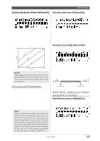
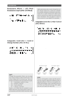
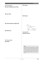
Multi Edit Mode Modulation Wheel - LFO Pitch Modulation Depth (MW LFOPMod) Range: 000 - 127 MIDI instruments allow you to change the control change number for a particular controller: for example, setting the modulation wheel (normally 01) to control Volume (07). Refer to the owner's manual of your particular instrument for more information. Also see page 62 in the VL Voice section for more details on controllers. This determines how widely the pitch is modulated by the LFO (low frequency oscillator). This is generally controlled from a modulation wheel on a MIDI keyboard and produces a vibrato effect. The higher the value, the deeper the pitch modulation, and hence, the more pronounced the vibrato effect. Assignable Controller 1 Control Change Number (AC1 CC No.) Range: 00 - 95 This determines the which MIDI control change number is assigned to the Assignable Controller (AC1) for the selected Part. AC1 can be used to affect the Filter (page 112), volume (Amplitude; page 113), LFO (page 133) or the Variation effect (page 145). Make sure that parameters you don't want to be affected by AC1 are properly set to 00. HINT Though this parameter allows you to assign any control change number from 0 to 95, only a few of these are in common use. The controllers most likely to be encountered include: 01 - Modulation wheel or lever 02 - Breath controller 04 - Foot controller 07 - Volume controller Some or all of these may be available on your MIDI instrument, and can be used to control certain functions on the MU100R in real time. Some Assignable Controller 1 Filter Control (AC1 FilCtrl) Range: -64 - +63 This determines the degree to which Assignable Controller 1 (AC1) affects the Cutoff Frequency of the Low Pass Filter for each Part. For maximum effect, this should be set to one of the extreme values, negative or positive. A setting of 00 results in no control over the Filter, even when AC1 is operated (or control change data is received). Negative settings affect the Filter negatively; in other words, when the controller is at the minimum position, control over the Filter is greatest (see illustration below). (The control number used for AC1 is set in the Assignable Controller 1 Control Change Number parameter above.) For positive values: For negative values: Minimum effect Maximum effect Maximum Minimum effect effect HINT Positive and negative values can be most effectively used by setting two different Parts to opposite settings. In this way, moving the controller (for example, a foot controller) one way will affect one Part and moving it the opposite way will affect the other Part. 112 Multi Mode
-
 1
1 -
2
-
3
-
4
-
5
-
6
-
7
-
8
-
9
-
10
-
11
-
12
-
13
-
14
-
15
-
16
-
17
-
18
-
19
-
20
-
21
-
22
-
23
-
24
-
25
-
26
-
27
-
28
-
29
-
30
-
31
-
32
-
33
-
34
-
35
-
36
-
37
-
38
-
39
-
40
-
41
-
42
-
43
-
44
-
45
-
46
-
47
-
48
-
49
-
50
-
51
-
52
-
53
-
54
-
55
-
56
-
57
-
58
-
59
-
60
-
61
-
62
-
63
-
64
-
65
-
66
-
67
-
68
-
69
-
70
-
71
-
72
-
73
-
74
-
75
-
76
-
77
-
78
-
79
-
80
-
81
-
82
-
83
-
84
-
85
-
86
-
87
-
88
-
89
-
90
-
91
-
92
-
93
-
94
-
95
-
96
-
97
-
98
-
99
-
100
-
101
-
102
-
103
-
104
-
105
-
106
-
107
-
108
-
109
-
110
-
111
-
112
-
113
-
114
-
115
-
116
-
117
-
 118
118 -
 119
119 -
 120
120 -
 121
121 -
 122
122 -
 123
123 -
 124
124 -
 125
125 -
 126
126 -
 127
127 -
 128
128 -
129
-
130
-
131
-
132
-
133
-
134
-
135
-
136
-
137
-
138
-
139
-
140
-
141
-
142
-
143
-
144
-
145
-
146
-
147
-
148
-
149
-
150
-
151
-
152
-
153
-
154
-
155
-
156
-
157
-
158
-
159
-
160
-
161
-
162
-
163
-
164
-
165
-
166
-
167
-
168
-
169
-
170
-
171
-
172
-
173
-
174
-
175
-
176
-
177
-
178
-
179
-
180
-
181
-
182
-
183
-
184
-
185
-
186
-
187
-
188
-
189
-
190
-
191
-
192
-
193
-
194
-
195
-
196
-
197
-
198
-
199
-
200
 |
 |
