Yamaha MU100R MU100R Owners Manual - Page 14
Rear Panel
 |
View all Yamaha MU100R manuals
Add to My Manuals
Save this manual to your list of manuals |
Page 14 highlights
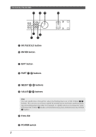
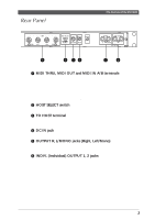
Rear Panel The Controls of the MU100R 1 2 34 56 1 MIDI THRU, MIDI OUT and MIDI IN A/B terminals For connection to other MIDI devices, such as a MIDI keyboard, tone generator, sequencer, or to a computer that has a MIDI interface. MIDI IN A and B are independent MIDI ports, allowing full 32-channel MIDI input. MIDI OUT is for data dumps to another MIDI device, while MIDI THRU is for "daisychain" connection of additional MU100Rs or other MIDI instruments. (See page 17 for more information on MIDI connections.) 2 HOST SELECT switch For selecting the type of host computer. (See page 19.) 3 TO HOST terminal For connection to a host computer that does not have a MIDI interface. (See page 19.) 4 DC IN jack For connection to the PA-5B AC power adaptor. 5 OUTPUT R, L/MONO jacks (Right, Left/Mono) For connection to a stereo amplifier/speaker system. When using a mono system, connect it to the L/MONO jack. 6 INDIV. (Individual) OUTPUT 1, 2 jacks For independent output of selected Parts (1/4" jack). Parts selected for output through these jacks are not output through the main OUTPUT or PHONES jacks. (See pages 113 and 118.) The Controls of the MU90R 3
-
 1
1 -
2
-
3
-
4
-
5
-
6
-
7
-
8
-
 9
9 -
 10
10 -
 11
11 -
 12
12 -
 13
13 -
 14
14 -
 15
15 -
 16
16 -
 17
17 -
 18
18 -
 19
19 -
20
-
21
-
22
-
23
-
24
-
25
-
26
-
27
-
28
-
29
-
30
-
31
-
32
-
33
-
34
-
35
-
36
-
37
-
38
-
39
-
40
-
41
-
42
-
43
-
44
-
45
-
46
-
47
-
48
-
49
-
50
-
51
-
52
-
53
-
54
-
55
-
56
-
57
-
58
-
59
-
60
-
61
-
62
-
63
-
64
-
65
-
66
-
67
-
68
-
69
-
70
-
71
-
72
-
73
-
74
-
75
-
76
-
77
-
78
-
79
-
80
-
81
-
82
-
83
-
84
-
85
-
86
-
87
-
88
-
89
-
90
-
91
-
92
-
93
-
94
-
95
-
96
-
97
-
98
-
99
-
100
-
101
-
102
-
103
-
104
-
105
-
106
-
107
-
108
-
109
-
110
-
111
-
112
-
113
-
114
-
115
-
116
-
117
-
118
-
119
-
120
-
121
-
122
-
123
-
124
-
125
-
126
-
127
-
128
-
129
-
130
-
131
-
132
-
133
-
134
-
135
-
136
-
137
-
138
-
139
-
140
-
141
-
142
-
143
-
144
-
145
-
146
-
147
-
148
-
149
-
150
-
151
-
152
-
153
-
154
-
155
-
156
-
157
-
158
-
159
-
160
-
161
-
162
-
163
-
164
-
165
-
166
-
167
-
168
-
169
-
170
-
171
-
172
-
173
-
174
-
175
-
176
-
177
-
178
-
179
-
180
-
181
-
182
-
183
-
184
-
185
-
186
-
187
-
188
-
189
-
190
-
191
-
192
-
193
-
194
-
195
-
196
-
197
-
198
-
199
-
200
 |
 |
