Yamaha MU100R MU100R Owners Manual - Page 124
Output Assignment
 |
View all Yamaha MU100R manuals
Add to My Manuals
Save this manual to your list of manuals |
Page 124 highlights
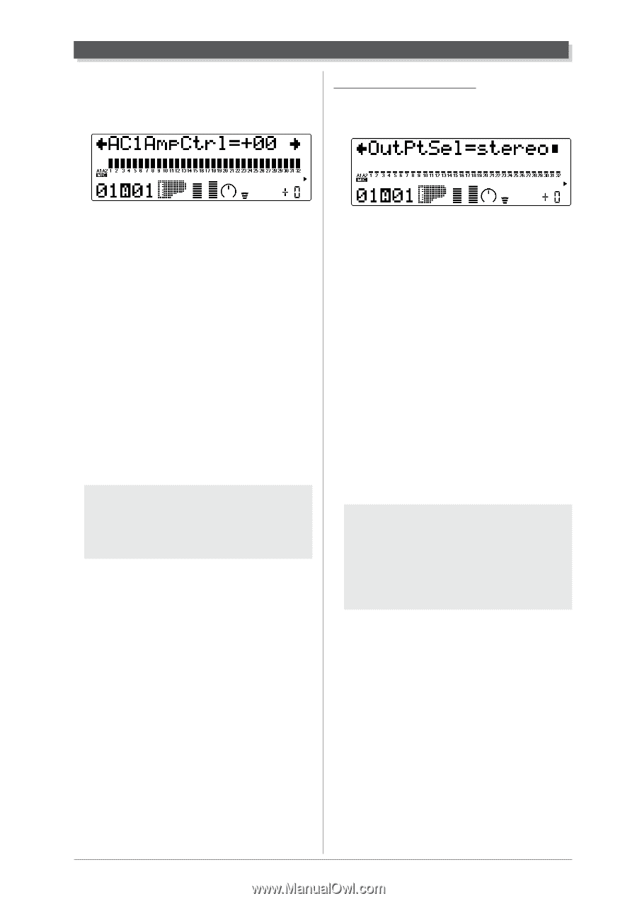
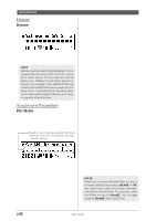
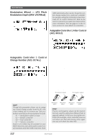
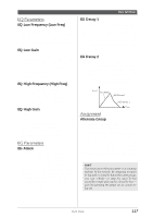
Multi Edit Mode Assignable Controller 1 Amplitude Control (AC1 AmpCtrl) Range: 64 - +63 Output Assignment Output Select (OutPtSel) Settings: stereo, ind1+2, ind1, ind2 This determines the degree to which Assignable Controller 1 (AC1) affects the volume (Amplitude) for each Part. For maximum effect, this should be set to one of the extreme values, negative or positive. A setting of 00 results in no volume control, even when AC1 is operated (or control change data is received). Negative settings affect the volume negatively; in other words, when the controller is at the minimum position, control over the volume is greatest. (The control number used for AC1 is set in the Assignable Controller 1 Control Change Number parameter above.) NOTE For more information on using positive and negative values, see the illustration and hint in Assignable Controller 1 Filter Control (page 112). This determines the output configuration for the selected Part. When set to "stereo," the Part is output (with effects) through the main OUTPUT and PHONES jacks. When set to one of the "ind" (individual) settings, it is output through the INDIV. OUTPUT jacks. In this case, only Insertion effects can be applied; System effects cannot be applied to the INDIV. OUTPUT jacks. When set to "ind1+2," the Part is output in stereo (1: left, 2: right). Settings of "ind1" and "ind2" output the Part in mono to the corresponding jack. (Parts output through the INDIV. OUTPUT jacks cannot be heard through the PHONES jack.) NOTE q The Output Select Lock parameter (page 158) must be set to "off" in order to change this setting via MIDI. q When the Part Mode parameter (page 108) is set to "drum" or "drum S1 - S4", this setting is inactive. Multi Mode 113
-
 1
1 -
2
-
3
-
4
-
5
-
6
-
7
-
8
-
9
-
10
-
11
-
12
-
13
-
14
-
15
-
16
-
17
-
18
-
19
-
20
-
21
-
22
-
23
-
24
-
25
-
26
-
27
-
28
-
29
-
30
-
31
-
32
-
33
-
34
-
35
-
36
-
37
-
38
-
39
-
40
-
41
-
42
-
43
-
44
-
45
-
46
-
47
-
48
-
49
-
50
-
51
-
52
-
53
-
54
-
55
-
56
-
57
-
58
-
59
-
60
-
61
-
62
-
63
-
64
-
65
-
66
-
67
-
68
-
69
-
70
-
71
-
72
-
73
-
74
-
75
-
76
-
77
-
78
-
79
-
80
-
81
-
82
-
83
-
84
-
85
-
86
-
87
-
88
-
89
-
90
-
91
-
92
-
93
-
94
-
95
-
96
-
97
-
98
-
99
-
100
-
101
-
102
-
103
-
104
-
105
-
106
-
107
-
108
-
109
-
110
-
111
-
112
-
113
-
114
-
115
-
116
-
117
-
118
-
 119
119 -
 120
120 -
 121
121 -
 122
122 -
 123
123 -
 124
124 -
 125
125 -
 126
126 -
 127
127 -
 128
128 -
 129
129 -
130
-
131
-
132
-
133
-
134
-
135
-
136
-
137
-
138
-
139
-
140
-
141
-
142
-
143
-
144
-
145
-
146
-
147
-
148
-
149
-
150
-
151
-
152
-
153
-
154
-
155
-
156
-
157
-
158
-
159
-
160
-
161
-
162
-
163
-
164
-
165
-
166
-
167
-
168
-
169
-
170
-
171
-
172
-
173
-
174
-
175
-
176
-
177
-
178
-
179
-
180
-
181
-
182
-
183
-
184
-
185
-
186
-
187
-
188
-
189
-
190
-
191
-
192
-
193
-
194
-
195
-
196
-
197
-
198
-
199
-
200
 |
 |