ZyXEL P-202H User Guide - Page 248
Filter Types and NAT
 |
View all ZyXEL P-202H manuals
Add to My Manuals
Save this manual to your list of manuals |
Page 248 highlights
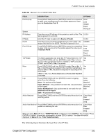
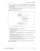
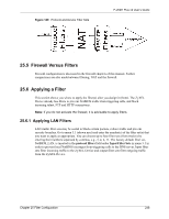
P-202H Plus v2 User's Guide Figure 148 Example Filter Rules Summary: Menu 21.1.3 Menu 21.1.3 - Filter Rules Summary # A Type Filter Rules M m n 1 Y IP Pr=6, SA=0.0.0.0, DA=0.0.0.0, DP=23 N D F 2 N 3 N 4 N 5 N 6 N Enter Filter Rule Number (1-6) to Configure: This shows you that you have configured and activated (A = Y) a TCP/IP filter rule (Type = IP, Pr = 6) for destination telnet ports (DP = 23). M = N means an action can be taken immediately. The action is to drop the packet (m = D) if the action is matched and to forward the packet immediately (n = F) if the action is not matched no matter whether there are more rules to be checked (there aren't in this example). After you've created the filter set, you must apply it. 1 Enter 11 from the main menu to go to menu 11. 2 Go to the Edit Filter Sets field, press [SPACE BAR] to select Yes and press [ENTER]. 3 This brings you to menu 11.5. Apply a filter set (our example filter set 3). 4 Press [ENTER] to confirm after you enter the set numbers and to leave menu 11.5. 25.4 Filter Types and NAT There are two classes of filter rules, Generic Filter (Device) rules and protocol filter (TCP/ IP) rules. Generic filter rules act on the raw data from/to LAN and WAN. Protocol filter rules act on the IP packets. Generic and TCP/IP filter rules are discussed in more detail in the next section. When NAT (Network Address Translation) is enabled, the inside IP address and port number are replaced on a connection-by-connection basis, which makes it impossible to know the exact address and port on the wire. Therefore, the ZyXEL Device applies the protocol filters to the "native" IP address and port number before NAT for outgoing packets and after NAT for incoming packets. On the other hand, the generic, or device filters are applied to the raw packets that appear on the wire. They are applied at the point when the ZyXEL Device is receiving and sending the packets; i.e. the interface. The interface can be an Ethernet port or any other hardware port. The following diagram illustrates this. 247 Chapter 25 Filter Configuration
-
 1
1 -
2
-
3
-
4
-
5
-
6
-
7
-
8
-
9
-
10
-
11
-
12
-
13
-
14
-
15
-
16
-
17
-
18
-
19
-
20
-
21
-
22
-
23
-
24
-
25
-
26
-
27
-
28
-
29
-
30
-
31
-
32
-
33
-
34
-
35
-
36
-
37
-
38
-
39
-
40
-
41
-
42
-
43
-
44
-
45
-
46
-
47
-
48
-
49
-
50
-
51
-
52
-
53
-
54
-
55
-
56
-
57
-
58
-
59
-
60
-
61
-
62
-
63
-
64
-
65
-
66
-
67
-
68
-
69
-
70
-
71
-
72
-
73
-
74
-
75
-
76
-
77
-
78
-
79
-
80
-
81
-
82
-
83
-
84
-
85
-
86
-
87
-
88
-
89
-
90
-
91
-
92
-
93
-
94
-
95
-
96
-
97
-
98
-
99
-
100
-
101
-
102
-
103
-
104
-
105
-
106
-
107
-
108
-
109
-
110
-
111
-
112
-
113
-
114
-
115
-
116
-
117
-
118
-
119
-
120
-
121
-
122
-
123
-
124
-
125
-
126
-
127
-
128
-
129
-
130
-
131
-
132
-
133
-
134
-
135
-
136
-
137
-
138
-
139
-
140
-
141
-
142
-
143
-
144
-
145
-
146
-
147
-
148
-
149
-
150
-
151
-
152
-
153
-
154
-
155
-
156
-
157
-
158
-
159
-
160
-
161
-
162
-
163
-
164
-
165
-
166
-
167
-
168
-
169
-
170
-
171
-
172
-
173
-
174
-
175
-
176
-
177
-
178
-
179
-
180
-
181
-
182
-
183
-
184
-
185
-
186
-
187
-
188
-
189
-
190
-
191
-
192
-
193
-
194
-
195
-
196
-
197
-
198
-
199
-
200
-
201
-
202
-
203
-
204
-
205
-
206
-
207
-
208
-
209
-
210
-
211
-
212
-
213
-
214
-
215
-
216
-
217
-
218
-
219
-
220
-
221
-
222
-
223
-
224
-
225
-
226
-
227
-
228
-
229
-
230
-
231
-
232
-
233
-
234
-
235
-
236
-
237
-
238
-
239
-
240
-
241
-
242
-
 243
243 -
 244
244 -
 245
245 -
 246
246 -
 247
247 -
 248
248 -
 249
249 -
 250
250 -
 251
251 -
 252
252 -
 253
253 -
254
-
255
-
256
-
257
-
258
-
259
-
260
-
261
-
262
-
263
-
264
-
265
-
266
-
267
-
268
-
269
-
270
-
271
-
272
-
273
-
274
-
275
-
276
-
277
-
278
-
279
-
280
-
281
-
282
-
283
-
284
-
285
-
286
-
287
-
288
-
289
-
290
-
291
-
292
-
293
-
294
-
295
-
296
-
297
-
298
-
299
-
300
-
301
-
302
-
303
-
304
-
305
-
306
-
307
-
308
-
309
-
310
-
311
-
312
-
313
-
314
-
315
-
316
-
317
-
318
-
319
-
320
-
321
-
322
-
323
-
324
-
325
-
326
-
327
-
328
-
329
-
330
-
331
-
332
-
333
-
334
-
335
-
336
-
337
-
338
-
339
-
340
-
341
-
342
-
343
-
344
-
345
-
346
-
347
-
348
-
349
-
350
-
351
-
352
-
353
-
354
-
355
-
356
-
357
-
358
-
359
-
360
-
361
-
362
-
363
-
364
-
365
-
366
-
367
-
368
-
369
-
370
-
371
-
372
-
373
-
374
-
375
 |
 |