Cisco 3825 Software Configuration Guide - Page 32
PVC Mapping, Asymmetric PWE3
 |
UPC - 746320981505
View all Cisco 3825 manuals
Add to My Manuals
Save this manual to your list of manuals |
Page 32 highlights
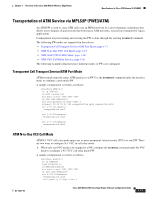
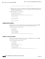
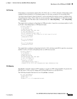
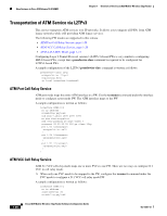
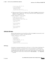
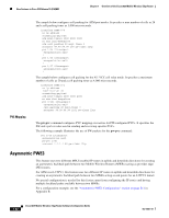
New Features in Cisco IOS Release 12.4(16)MR1 Chapter 1 Overview of the Cisco 3825 Mobile Wireless Edge Router PVC Mapping The sample below configures cell packing for ATM port modes. It specifies a max number of cells as 28 and a cell packing timer as 3,000 microseconds. interface ATM0/0/0 no ip address scrambling-payload atm mcpt-timers 1000 2000 3000 no atm ilmi-keepalive atm cell-packing 28 mcpt-timer 3 xconnect 99.99.99.99 100 pw-class l2tp pvc 1/35 l2transport encapsulation aal0 ! pvc 1/36 l2transport encapsulation aal0 ! pvc 1/37 l2transport encapsulation aal0 ! The sample below configures cell packing for the N:1 VCC cell relay mode. It specifies a maximum number of cells as 20 and a cell packing timer as 4,000 microseconds. interface ATM0/0/1 no ip address load-interval 30 scrambling-payload atm mcpt-timers 2000 3000 4000 no atm ilmi-keepalive pvc 0/101 l2transport encapsulation aal0 cell-packing 20 mcpt-timer 3 xconnect 99.99.99.99 1101 pw-class l2tp The pw-pvc command configures PVC mapping or rewrites for PW-configured PVCs. It specifies the PW-side vpi/vci value used in sending and receiving specific PVCs. The following example illustrates the use of PW packets for the pw-pvc command: pvc 0/40 l2transport encapsulation aal0 pw-pvc 1/40 xconnect 1.1.1.1 40 pw-class l2tp Asymmetric PWE3 This feature uses two different MPLS enabled IP routes in uplink and downlink directions for creating an asymmetric backhaul path between two Mobile Wireless Routers (MWRs) acting as provider edge (PE) routers. For ATM over L2TPV3, this feature uses two different IP routes in uplink and downlink directions for creating an asymmetric backhaul path between two MWRs acting as end points for an L2TPV3 tunnel. No special configuration is needed for this feature apart from configuring the IP routes and having multiple backhaul paths available between two MWRs. For a configuration example, see the "Asymmetric PWE3 Configuration" section on page B-2 in Appendix B. 1-22 Cisco 3825 Mobile Wireless Edge Router Software Configuration Guide OL-15667-03
-
 1
1 -
2
-
3
-
4
-
5
-
6
-
7
-
8
-
9
-
10
-
11
-
12
-
13
-
14
-
15
-
16
-
17
-
18
-
19
-
20
-
21
-
22
-
23
-
24
-
25
-
26
-
 27
27 -
 28
28 -
 29
29 -
 30
30 -
 31
31 -
 32
32 -
 33
33 -
 34
34 -
 35
35 -
 36
36 -
 37
37 -
38
-
39
-
40
-
41
-
42
-
43
-
44
-
45
-
46
-
47
-
48
-
49
-
50
-
51
-
52
-
53
-
54
-
55
-
56
-
57
-
58
-
59
-
60
-
61
-
62
-
63
-
64
-
65
-
66
-
67
-
68
-
69
-
70
-
71
-
72
-
73
-
74
-
75
-
76
-
77
-
78
-
79
-
80
-
81
-
82
-
83
-
84
-
85
-
86
-
87
-
88
-
89
-
90
-
91
-
92
-
93
-
94
-
95
-
96
-
97
-
98
-
99
-
100
-
101
-
102
-
103
-
104
-
105
-
106
-
107
-
108
-
109
-
110
-
111
-
112
-
113
-
114
-
115
-
116
-
117
-
118
-
119
-
120
-
121
-
122
-
123
-
124
-
125
-
126
-
127
-
128
-
129
-
130
-
131
-
132
-
133
-
134
-
135
-
136
-
137
-
138
-
139
-
140
-
141
-
142
-
143
-
144
-
145
-
146
-
147
-
148
-
149
-
150
-
151
-
152
-
153
-
154
-
155
-
156
-
157
-
158
-
159
-
160
-
161
-
162
-
163
-
164
-
165
-
166
-
167
-
168
-
169
-
170
-
171
-
172
-
173
-
174
-
175
-
176
-
177
-
178
-
179
-
180
-
181
-
182
-
183
-
184
-
185
-
186
-
187
-
188
-
189
-
190
-
191
-
192
-
193
-
194
-
195
-
196
-
197
-
198
-
199
-
200
-
201
-
202
-
203
-
204
-
205
-
206
-
207
-
208
-
209
-
210
-
211
-
212
-
213
-
214
-
215
-
216
-
217
-
218
-
219
-
220
-
221
-
222
-
223
-
224
-
225
-
226
-
227
-
228
-
229
-
230
-
231
-
232
-
233
-
234
-
235
-
236
-
237
-
238
-
239
-
240
-
241
-
242
-
243
-
244
-
245
-
246
-
247
-
248
-
249
-
250
-
251
-
252
-
253
-
254
-
255
-
256
-
257
-
258
-
259
-
260
-
261
-
262
-
263
-
264
-
265
-
266
-
267
-
268
-
269
-
270
-
271
-
272
-
273
-
274
-
275
-
276
-
277
-
278
-
279
-
280
-
281
-
282
-
283
-
284
-
285
-
286
-
287
-
288
-
289
-
290
-
291
-
292
-
293
-
294
-
295
-
296
-
297
-
298
-
299
-
300
-
301
-
302
-
303
-
304
-
305
-
306
-
307
-
308
-
309
-
310
-
311
-
312
-
313
-
314
-
315
-
316
-
317
-
318
-
319
-
320
-
321
-
322
-
323
-
324
-
325
-
326
-
327
-
328
-
329
-
330
-
331
-
332
-
333
-
334
-
335
-
336
-
337
-
338
-
339
-
340
-
341
-
342
-
343
-
344
-
345
-
346
-
347
-
348
-
349
-
350
-
351
-
352
-
353
-
354
-
355
-
356
-
357
-
358
 |
 |