Cisco 3825 Software Configuration Guide - Page 97
NBAP and Access Link Control Application Part ALCAP PVCs can be defined using qsaal
 |
UPC - 746320981505
View all Cisco 3825 manuals
Add to My Manuals
Save this manual to your list of manuals |
Page 97 highlights
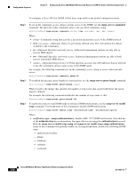
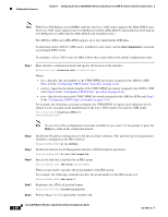
Chapter 4 Configuring the Cisco 3825 Mobile Wireless Edge Router in a RAN-O Solution with the Command-Line Configuration Sequence Step 7 Specify the slot location and port of IMA interface group. Router(config-if)# interface ATMslot/IMA Where: • slot-Specifies the slot location of the ATM IMA port adapter. • group-number-Specifies the group number of the IMA group. For example, the following command specifies the slot number as 0 and the group number as 0: Router(config-if)# interface ATM0/IMA0 Note Should you desire, the optional ima group-id command can be used to explicitly configure the IMA Group ID for the IMA interface. You cannot configure the same IMA Group ID on two different IMA interfaces; therefore, if you configure an IMA Group ID with the system-selected default ID already configured on an IMA interface, the system toggles the IMA interface to make the user-configured IMA Group ID the effective IMA Group ID. At the same, the system toggles the original IMA interface to select a different IMA Group ID. Step 8 Disable the IP address configuration for the physical layer interface. Router(config-if)# no ip address Step 9 Specify the ATM bandwith as dynamic. Router(config-if)# atm bandwith dynamic Step 10 Create an ATM path on the UMTS Iub interface, enter the following command: Router(config-if)# atm umts-iub Step 11 Disable the Interim Local Management Interface (ILMI) keepalive parameters. Router(config-if)# no atm ilmi-keepalive Step 12 Create an ATM PVC: Router(config-if)# pvc [name] vpi/vci [qsaal] Where: • name-(Optional) specifies the name of the ATM PVC interface you create. • vpi-Specifies the ATM network virtual path identifier (VPI) of this PVC. • vci-Specifies the ATM network virtual channel identifier (VCI) of this PVC. • qsaal-(Optional) specifies theQ.2931 signaling ATM adaptation layer (QSAAL) encapsulation type. Note Typically AAL5 PVCs are defined using qsaal encapsulation. However, if the traffic profile is such that the AAL5 packets exceed normal signaling (272 bytes) payload size, it is recommended that the PVC be defined using AAL0. This is commonly true for OAM PVCs and synchronization PVCs. NodeB Application Part (NBAP) and Access Link Control Application Part (ALCAP) PVCs can be defined using qsaal encapsulation. OL-15667-03 Cisco 3825 Mobile Wireless Edge Router Software Configuration Guide 4-39
-
 1
1 -
2
-
3
-
4
-
5
-
6
-
7
-
8
-
9
-
10
-
11
-
12
-
13
-
14
-
15
-
16
-
17
-
18
-
19
-
20
-
21
-
22
-
23
-
24
-
25
-
26
-
27
-
28
-
29
-
30
-
31
-
32
-
33
-
34
-
35
-
36
-
37
-
38
-
39
-
40
-
41
-
42
-
43
-
44
-
45
-
46
-
47
-
48
-
49
-
50
-
51
-
52
-
53
-
54
-
55
-
56
-
57
-
58
-
59
-
60
-
61
-
62
-
63
-
64
-
65
-
66
-
67
-
68
-
69
-
70
-
71
-
72
-
73
-
74
-
75
-
76
-
77
-
78
-
79
-
80
-
81
-
82
-
83
-
84
-
85
-
86
-
87
-
88
-
89
-
90
-
91
-
 92
92 -
 93
93 -
 94
94 -
 95
95 -
 96
96 -
 97
97 -
 98
98 -
 99
99 -
 100
100 -
 101
101 -
 102
102 -
103
-
104
-
105
-
106
-
107
-
108
-
109
-
110
-
111
-
112
-
113
-
114
-
115
-
116
-
117
-
118
-
119
-
120
-
121
-
122
-
123
-
124
-
125
-
126
-
127
-
128
-
129
-
130
-
131
-
132
-
133
-
134
-
135
-
136
-
137
-
138
-
139
-
140
-
141
-
142
-
143
-
144
-
145
-
146
-
147
-
148
-
149
-
150
-
151
-
152
-
153
-
154
-
155
-
156
-
157
-
158
-
159
-
160
-
161
-
162
-
163
-
164
-
165
-
166
-
167
-
168
-
169
-
170
-
171
-
172
-
173
-
174
-
175
-
176
-
177
-
178
-
179
-
180
-
181
-
182
-
183
-
184
-
185
-
186
-
187
-
188
-
189
-
190
-
191
-
192
-
193
-
194
-
195
-
196
-
197
-
198
-
199
-
200
-
201
-
202
-
203
-
204
-
205
-
206
-
207
-
208
-
209
-
210
-
211
-
212
-
213
-
214
-
215
-
216
-
217
-
218
-
219
-
220
-
221
-
222
-
223
-
224
-
225
-
226
-
227
-
228
-
229
-
230
-
231
-
232
-
233
-
234
-
235
-
236
-
237
-
238
-
239
-
240
-
241
-
242
-
243
-
244
-
245
-
246
-
247
-
248
-
249
-
250
-
251
-
252
-
253
-
254
-
255
-
256
-
257
-
258
-
259
-
260
-
261
-
262
-
263
-
264
-
265
-
266
-
267
-
268
-
269
-
270
-
271
-
272
-
273
-
274
-
275
-
276
-
277
-
278
-
279
-
280
-
281
-
282
-
283
-
284
-
285
-
286
-
287
-
288
-
289
-
290
-
291
-
292
-
293
-
294
-
295
-
296
-
297
-
298
-
299
-
300
-
301
-
302
-
303
-
304
-
305
-
306
-
307
-
308
-
309
-
310
-
311
-
312
-
313
-
314
-
315
-
316
-
317
-
318
-
319
-
320
-
321
-
322
-
323
-
324
-
325
-
326
-
327
-
328
-
329
-
330
-
331
-
332
-
333
-
334
-
335
-
336
-
337
-
338
-
339
-
340
-
341
-
342
-
343
-
344
-
345
-
346
-
347
-
348
-
349
-
350
-
351
-
352
-
353
-
354
-
355
-
356
-
357
-
358
 |
 |