Cisco SPA112 Administration Guide - Page 56
Voice System Settings, Configuring Voice, Logging, Field, Description - review
 |
View all Cisco SPA112 manuals
Add to My Manuals
Save this manual to your list of manuals |
Page 56 highlights
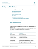
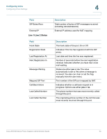
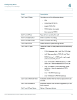
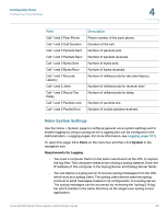
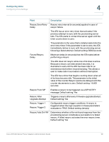
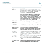
Configuring Voice Configuring Voice Settings 4 Field Call 1 and 2 Peer Phone Call 1 and 2 Call Duration Call 1 and 2 Packets Sent Call 1 and 2 Packets Recv Call 1 and 2 Bytes Sent Call 1 and 2 Bytes Recv Call 1 and 2 Decode Latency Call 1 and 2 Jitter Call 1 and 2 Round Trip Delay Call 1 and 2 Packets Lost Call 1 and 2 Packet Error Description Phone number of the peer phone. Duration of the call. Number of packets sent Number of packets received. Number of bytes sent. Number of bytes received. Number of milliseconds for decoder latency. Number of milliseconds for receiver jitter Number of milliseconds for delay. Number of packets lost. Number of invalid packets received. Voice System Settings Use the Voice > System page to configure general voice system settings and to enable logging by using a syslog server. (Logging also can be configured in the Administration > Logging pages. For more information, see Logging, page 121.) To open this page: Click Voice on the menu bar, and then click System in the navigation tree. Requirements for Logging • You need a computer that is on the same subnetwork as the ATA, to capture the log files. This computer needs to be running a syslog daemon. Enter the IP address of this computer in the Syslog Server and Debug Server fields. • You can deploy a syslog server to receive syslog messages from the ATA, which acts as a syslog client. The syslog client device uses the syslog protocol to send messages, based on its configuration, to a syslog server. The syslog messages can be accessed by reviewing the "syslog.514.log" file which resides in the same directory as the slogsrv.exe syslog server application. Cisco SPA100 Series Phone Adapters Administration Guide 56
-
 1
1 -
2
-
3
-
4
-
5
-
6
-
7
-
8
-
9
-
10
-
11
-
12
-
13
-
14
-
15
-
16
-
17
-
18
-
19
-
20
-
21
-
22
-
23
-
24
-
25
-
26
-
27
-
28
-
29
-
30
-
31
-
32
-
33
-
34
-
35
-
36
-
37
-
38
-
39
-
40
-
41
-
42
-
43
-
44
-
45
-
46
-
47
-
48
-
49
-
50
-
 51
51 -
 52
52 -
 53
53 -
 54
54 -
 55
55 -
 56
56 -
 57
57 -
 58
58 -
 59
59 -
 60
60 -
 61
61 -
62
-
63
-
64
-
65
-
66
-
67
-
68
-
69
-
70
-
71
-
72
-
73
-
74
-
75
-
76
-
77
-
78
-
79
-
80
-
81
-
82
-
83
-
84
-
85
-
86
-
87
-
88
-
89
-
90
-
91
-
92
-
93
-
94
-
95
-
96
-
97
-
98
-
99
-
100
-
101
-
102
-
103
-
104
-
105
-
106
-
107
-
108
-
109
-
110
-
111
-
112
-
113
-
114
-
115
-
116
-
117
-
118
-
119
-
120
-
121
-
122
-
123
-
124
-
125
-
126
-
127
-
128
-
129
-
130
-
131
-
132
-
133
-
134
-
135
-
136
-
137
-
138
-
139
-
140
-
141
-
142
-
143
-
144
-
145
-
146
-
147
 |
 |