Dell PowerVault 56F Dell PowerVault 51F 8-Port Fibre Channel Switch Insta - Page 115
Installing a System Board, Removing the System Board
 |
View all Dell PowerVault 56F manuals
Add to My Manuals
Save this manual to your list of manuals |
Page 115 highlights
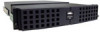
10. Remove the new system board from its antistatic bag and place the old system board into the bag. Figure 6-6. Removing the System Board Installing a System Board 1. Lay the serial port cable to the outside of the unit over the power supply. 2. Tilt the front end of the system board about 45 degrees and slide it into the front panel. Then lower the back end of the system board so that the metal guides on the chassis fit into the slots on the system board. 3. Slide the system board forward up against the front panel until the screw holes line up. 4. Install the four Phillips screws into the system board. The #4 Phillips-head screw goes into the center back hole on the system board and the #2 Phillips-head screws go into the three holes at the front of the system board. 5. Reconnect the serial port ribbon cable to the system board. The cable is keyed with the red strip going to pin 1 on the connector. Gently lay the excess ribbon cable between the system board and chassis to prevent cable damage. 6. Reconnect the power supply connector(s). 7. Reconnect the fan tray assembly connector. 8. Replace the switch's cover. support.dell.com Repair and Replacement 6-7
-
 1
1 -
2
-
3
-
4
-
5
-
6
-
7
-
8
-
9
-
10
-
11
-
12
-
13
-
14
-
15
-
16
-
17
-
18
-
19
-
20
-
21
-
22
-
23
-
24
-
25
-
26
-
27
-
28
-
29
-
30
-
31
-
32
-
33
-
34
-
35
-
36
-
37
-
38
-
39
-
40
-
41
-
42
-
43
-
44
-
45
-
46
-
47
-
48
-
49
-
50
-
51
-
52
-
53
-
54
-
55
-
56
-
57
-
58
-
59
-
60
-
61
-
62
-
63
-
64
-
65
-
66
-
67
-
68
-
69
-
70
-
71
-
72
-
73
-
74
-
75
-
76
-
77
-
78
-
79
-
80
-
81
-
82
-
83
-
84
-
85
-
86
-
87
-
88
-
89
-
90
-
91
-
92
-
93
-
94
-
95
-
96
-
97
-
98
-
99
-
100
-
101
-
102
-
103
-
104
-
105
-
106
-
107
-
108
-
109
-
 110
110 -
 111
111 -
 112
112 -
 113
113 -
 114
114 -
 115
115 -
 116
116 -
 117
117 -
 118
118 -
 119
119 -
 120
120 -
121
-
122
-
123
-
124
-
125
-
126
-
127
-
128
-
129
-
130
-
131
-
132
-
133
-
134
-
135
-
136
-
137
-
138
-
139
-
140
-
141
-
142
-
143
-
144
-
145
-
146
-
147
-
148
-
149
-
150
-
151
-
152
-
153
-
154
-
155
-
156
 |
 |
