Dell PowerVault 56F Dell PowerVault 51F 8-Port Fibre Channel Switch Insta - Page 45
Setting IP Address Using the Serial Port, Flow control = Xon/Xoff
 |
View all Dell PowerVault 56F manuals
Add to My Manuals
Save this manual to your list of manuals |
Page 45 highlights
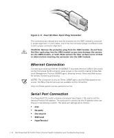
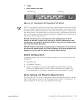
If error conditions are encountered, they are displayed on the local RS-232 serial port after the switch completes the POST. See "errShow" in Chapter 4 for details. Setting IP Address Using the Serial Port There is a label on the front panel of the PowerVault 51F switch with space to include the IP address after it has been configured. NOTE: This label facilitates identification of the physical switch in maintenance mode. To enable a connection to the switch, the switch must have a valid IP address set. Two IP addresses can be set-one for the external out-of-band Ethernet port and one for in-band Fibre Channel network (IP) access. The serial port is initially logged on as admin with no password required. To set the IP address using the serial port, perform the following steps: 1. Connect the DB9 serial cable from the computer's COM port to the switch's RS-232 port. 2. Start the HyperTerminal by selecting Programs-> Accessories-> HyperTerminal and then hyperterm.exe. Supply a name in the Connection Description dialog box. Enter Direct to Com in the Connect Using dialog box. The COM Properties dialog box is displayed with the following settings: • 8-bit • No parity • One stop bit • 9600 baud • HyperTerminal • VT100 • Flow control = Xon/Xoff 3. Turn on the switch and read the messages on the screen. 4. As the admin user, type ipAddrSet and press . The following text appears: Ethernet IP Address [current address shown]: [enter new address if needed] Ethernet Subnetmaks [current]: [enter new subnet mask if needed] Fibre Channel IP Address [current]: [enter new address if needed] support.dell.com Installing the Dell PowerVault 51F Switch 1-17
-
 1
1 -
2
-
3
-
4
-
5
-
6
-
7
-
8
-
9
-
10
-
11
-
12
-
13
-
14
-
15
-
16
-
17
-
18
-
19
-
20
-
21
-
22
-
23
-
24
-
25
-
26
-
27
-
28
-
29
-
30
-
31
-
32
-
33
-
34
-
35
-
36
-
37
-
38
-
39
-
 40
40 -
 41
41 -
 42
42 -
 43
43 -
 44
44 -
 45
45 -
 46
46 -
 47
47 -
 48
48 -
 49
49 -
 50
50 -
51
-
52
-
53
-
54
-
55
-
56
-
57
-
58
-
59
-
60
-
61
-
62
-
63
-
64
-
65
-
66
-
67
-
68
-
69
-
70
-
71
-
72
-
73
-
74
-
75
-
76
-
77
-
78
-
79
-
80
-
81
-
82
-
83
-
84
-
85
-
86
-
87
-
88
-
89
-
90
-
91
-
92
-
93
-
94
-
95
-
96
-
97
-
98
-
99
-
100
-
101
-
102
-
103
-
104
-
105
-
106
-
107
-
108
-
109
-
110
-
111
-
112
-
113
-
114
-
115
-
116
-
117
-
118
-
119
-
120
-
121
-
122
-
123
-
124
-
125
-
126
-
127
-
128
-
129
-
130
-
131
-
132
-
133
-
134
-
135
-
136
-
137
-
138
-
139
-
140
-
141
-
142
-
143
-
144
-
145
-
146
-
147
-
148
-
149
-
150
-
151
-
152
-
153
-
154
-
155
-
156
 |
 |
