Dell PowerVault 56F Dell PowerVault 51F 8-Port Fibre Channel Switch Insta - Page 44
Verifying Power-On Self-Test (POST), Table 1-2., Cabling Pinouts
 |
View all Dell PowerVault 56F manuals
Add to My Manuals
Save this manual to your list of manuals |
Page 44 highlights
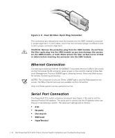
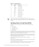
Table 1-2. Cabling Pinouts Pin Signal Description 1 DCD Carrier Detect 2 TxData Transmit Data 3 RxData Receive Data 4 DTR Data Terminal Ready 5 GND Logic Ground 6 DSR Data Set Ready 7 RTS Request to Send 8 CTS Clear To Send 9 RI Ring Indicator NOTE: For dust and electrostatic discharge (ESD) protection, the PowerVault 51F switch includes a cover for the serial port. When not in use, the serial port should be covered. Verifying Power-On Self-Test (POST) When powering on a switch, the switch conducts a series of diagnostic tests including: • Memory Test • Port Register Test • Central Memory Test • RDRAM Test POST behaves differently depending on the boot method. A power cycle (power off and power on) is considered a cold boot. All other boots from a powered-on state (per reboot, panic, and so on) are considered to be warm boots. POST execution per cold boot executes the long version of the memory test. POST execution per warm boot executes a shorter version of memory test. Boot time with POST varies depending on the boot method. As the POST successfully performs each of the tests, the message Passed is displayed via Telnet. After the switch completes the POST, the GBIC module returns to a steady state from the flashing states shown during the tests. If an amber GBIC module light is displayed, there was a failure on that port during POST. See "Power-On Diagnostics" in Chapter 5 for more information. 1-16 Dell PowerVault 51F 8-Port Fibre Channel Switch Installation and Troubleshooting Guide
-
 1
1 -
2
-
3
-
4
-
5
-
6
-
7
-
8
-
9
-
10
-
11
-
12
-
13
-
14
-
15
-
16
-
17
-
18
-
19
-
20
-
21
-
22
-
23
-
24
-
25
-
26
-
27
-
28
-
29
-
30
-
31
-
32
-
33
-
34
-
35
-
36
-
37
-
38
-
 39
39 -
 40
40 -
 41
41 -
 42
42 -
 43
43 -
 44
44 -
 45
45 -
 46
46 -
 47
47 -
 48
48 -
 49
49 -
50
-
51
-
52
-
53
-
54
-
55
-
56
-
57
-
58
-
59
-
60
-
61
-
62
-
63
-
64
-
65
-
66
-
67
-
68
-
69
-
70
-
71
-
72
-
73
-
74
-
75
-
76
-
77
-
78
-
79
-
80
-
81
-
82
-
83
-
84
-
85
-
86
-
87
-
88
-
89
-
90
-
91
-
92
-
93
-
94
-
95
-
96
-
97
-
98
-
99
-
100
-
101
-
102
-
103
-
104
-
105
-
106
-
107
-
108
-
109
-
110
-
111
-
112
-
113
-
114
-
115
-
116
-
117
-
118
-
119
-
120
-
121
-
122
-
123
-
124
-
125
-
126
-
127
-
128
-
129
-
130
-
131
-
132
-
133
-
134
-
135
-
136
-
137
-
138
-
139
-
140
-
141
-
142
-
143
-
144
-
145
-
146
-
147
-
148
-
149
-
150
-
151
-
152
-
153
-
154
-
155
-
156
 |
 |
