Dell PowerVault 56F Dell PowerVault 51F 8-Port Fibre Channel Switch Insta - Page 36
Adjusting the Bezel Position, Installing the Outer Slides,
 |
View all Dell PowerVault 56F manuals
Add to My Manuals
Save this manual to your list of manuals |
Page 36 highlights
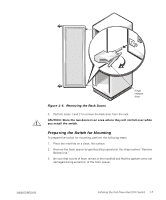
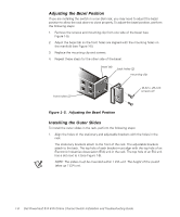
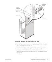
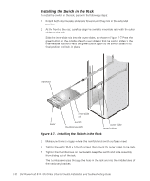
Adjusting the Bezel Position If you are installing the switch in a non-Dell rack, you may need to adjust the bezel position to allow the rack doors to close properly. To adjust the bezel position, perform the following steps: 1. Remove the screws and mounting clip from one side of the bezel (see Figure 1-5). 2. Adjust the bezel tab so the front holes are aligned with the mounting holes on the manifold (see Figure 1-5). 3. Replace the mounting clip and screws. 4. Repeat these steps for the other side of the bezel. bezel tab back holes (2) mounting clip front holes (2) 10-32 x .25-inch screws (2) Figure 1-5. Adjusting the Bezel Position Installing the Outer Slides To install the outer slides in the rack, perform the following steps: 1. Align the holes of the stationary and adjustable brackets with the holes in the rack. The stationary brackets attach to the front of the rack. The adjustable brackets attach to the back. The top hole of each bracket must align with the top hole of an Electronic Industries Association (EIA) unit in the rack. The top hole of an EIA unit has a dot next to it (see Figure 1-6). NOTE: The slides must be mounted within 1 EIA unit. The height of the switch takes up 1 EIA unit. 1-8 Dell PowerVault 51F 8-Port Fibre Channel Switch Installation and Troubleshooting Guide
-
 1
1 -
2
-
3
-
4
-
5
-
6
-
7
-
8
-
9
-
10
-
11
-
12
-
13
-
14
-
15
-
16
-
17
-
18
-
19
-
20
-
21
-
22
-
23
-
24
-
25
-
26
-
27
-
28
-
29
-
30
-
 31
31 -
 32
32 -
 33
33 -
 34
34 -
 35
35 -
 36
36 -
 37
37 -
 38
38 -
 39
39 -
 40
40 -
 41
41 -
42
-
43
-
44
-
45
-
46
-
47
-
48
-
49
-
50
-
51
-
52
-
53
-
54
-
55
-
56
-
57
-
58
-
59
-
60
-
61
-
62
-
63
-
64
-
65
-
66
-
67
-
68
-
69
-
70
-
71
-
72
-
73
-
74
-
75
-
76
-
77
-
78
-
79
-
80
-
81
-
82
-
83
-
84
-
85
-
86
-
87
-
88
-
89
-
90
-
91
-
92
-
93
-
94
-
95
-
96
-
97
-
98
-
99
-
100
-
101
-
102
-
103
-
104
-
105
-
106
-
107
-
108
-
109
-
110
-
111
-
112
-
113
-
114
-
115
-
116
-
117
-
118
-
119
-
120
-
121
-
122
-
123
-
124
-
125
-
126
-
127
-
128
-
129
-
130
-
131
-
132
-
133
-
134
-
135
-
136
-
137
-
138
-
139
-
140
-
141
-
142
-
143
-
144
-
145
-
146
-
147
-
148
-
149
-
150
-
151
-
152
-
153
-
154
-
155
-
156
 |
 |
