Dell PowerVault 56F Dell PowerVault 51F 8-Port Fibre Channel Switch Insta - Page 49
Sample Fabric Topologies, Single-Switch Fabric
 |
View all Dell PowerVault 56F manuals
Add to My Manuals
Save this manual to your list of manuals |
Page 49 highlights
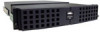
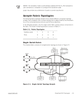
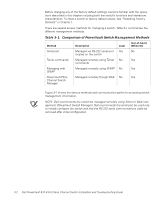
FILE LOCATION: S:\SYSTEMS\Boxer\rev_i&t\English\50UWDa00\50UWDc20.fm NOTES: The translative mode is automatically enabled with the FL_Port card and no user intervention is necessary to configure the translative mode. Loops may contain any combination of public or private loop devices. Sample Fabric Topologies The following fabric topology samples show several different conceptual topology models. Each installation has a unique topology that is determined by the characteristics of the connected devices and your performance objectives. In the following samples, only the single switch fabric solution shows connections to the fabric. The switch numbering scheme is shown in Table 2-1. Table 2-1. Fabric Topologies Interface cards 1 2 3 4 Ports 0 2 4 6 1 3 5 7 Single-Switch Fabric The simplest fabric consists of a single-switch topology as shown in Figure 2-1. JBOD fabric N_Port Data F_Port Mainframe N_Port FL_Port NL_Ports F_Port JBOD NL_Ports FL_Port F_Port F_Port F_Port N_Port Data N_Port Data Figure 2-1. Single-Switch Topology Sample N_Port Mainframe support.dell.com DELL CONFIDENTIAL - Preliminary 4/6/00 PowerVault 51F Topologies 2-3
-
 1
1 -
2
-
3
-
4
-
5
-
6
-
7
-
8
-
9
-
10
-
11
-
12
-
13
-
14
-
15
-
16
-
17
-
18
-
19
-
20
-
21
-
22
-
23
-
24
-
25
-
26
-
27
-
28
-
29
-
30
-
31
-
32
-
33
-
34
-
35
-
36
-
37
-
38
-
39
-
40
-
41
-
42
-
43
-
 44
44 -
 45
45 -
 46
46 -
 47
47 -
 48
48 -
 49
49 -
 50
50 -
 51
51 -
 52
52 -
 53
53 -
 54
54 -
55
-
56
-
57
-
58
-
59
-
60
-
61
-
62
-
63
-
64
-
65
-
66
-
67
-
68
-
69
-
70
-
71
-
72
-
73
-
74
-
75
-
76
-
77
-
78
-
79
-
80
-
81
-
82
-
83
-
84
-
85
-
86
-
87
-
88
-
89
-
90
-
91
-
92
-
93
-
94
-
95
-
96
-
97
-
98
-
99
-
100
-
101
-
102
-
103
-
104
-
105
-
106
-
107
-
108
-
109
-
110
-
111
-
112
-
113
-
114
-
115
-
116
-
117
-
118
-
119
-
120
-
121
-
122
-
123
-
124
-
125
-
126
-
127
-
128
-
129
-
130
-
131
-
132
-
133
-
134
-
135
-
136
-
137
-
138
-
139
-
140
-
141
-
142
-
143
-
144
-
145
-
146
-
147
-
148
-
149
-
150
-
151
-
152
-
153
-
154
-
155
-
156
 |
 |
