Dell PowerVault 56F Dell PowerVault 51F 8-Port Fibre Channel Switch Insta - Page 42
Ethernet Connection, Serial Port Connection, Dual SC Fiber-Optic Plug Connector
 |
View all Dell PowerVault 56F manuals
Add to My Manuals
Save this manual to your list of manuals |
Page 42 highlights
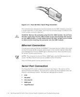
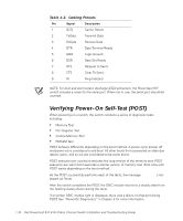
Figure 1-9. Dual SC Fiber-Optic Plug Connector The connectors are indexed and must be inserted into the GBIC module's connector in proper alignment. In most cases, one of the two connector plugs is a different color to aid in proper connector alignment. CAUTION: Remove the protective plug from the GBIC module. Do not force the fiber-optic plug into the GBIC module as you may damage the connector, the GBIC module, or both. Make certain the fiber surface is free of dust or debris before inserting the connector into the GBIC module. Ethernet Connection Connecting an existing Ethernet 10/100BASE-T local area network (LAN) to the switch via the front panel RJ-45 connector gives access to the switch's internal Simple Network Management Protocol (SNMP) agent, allowing remote Telnet and Web access for remote monitoring and testing. NOTES: The connection is only for Telnet, SNMP agent, and the Web-based server access. No Fibre Channel services are available via this connection. Only one Telnet session can be opened at a time. Serial Port Connection The PowerVault 51F switch includes a serial port (see Figure 1-10) used to set the Internet Protocol (IP) address. The serial port is used to set the IP address when setting up or reinitializing a switch. The serial port settings are as follows: • 8 bit • No parity • One stop bit • 9600 baud • HyperTerminal 1-14 Dell PowerVault 51F 8-Port Fibre Channel Switch Installation and Troubleshooting Guide
-
 1
1 -
2
-
3
-
4
-
5
-
6
-
7
-
8
-
9
-
10
-
11
-
12
-
13
-
14
-
15
-
16
-
17
-
18
-
19
-
20
-
21
-
22
-
23
-
24
-
25
-
26
-
27
-
28
-
29
-
30
-
31
-
32
-
33
-
34
-
35
-
36
-
 37
37 -
 38
38 -
 39
39 -
 40
40 -
 41
41 -
 42
42 -
 43
43 -
 44
44 -
 45
45 -
 46
46 -
 47
47 -
48
-
49
-
50
-
51
-
52
-
53
-
54
-
55
-
56
-
57
-
58
-
59
-
60
-
61
-
62
-
63
-
64
-
65
-
66
-
67
-
68
-
69
-
70
-
71
-
72
-
73
-
74
-
75
-
76
-
77
-
78
-
79
-
80
-
81
-
82
-
83
-
84
-
85
-
86
-
87
-
88
-
89
-
90
-
91
-
92
-
93
-
94
-
95
-
96
-
97
-
98
-
99
-
100
-
101
-
102
-
103
-
104
-
105
-
106
-
107
-
108
-
109
-
110
-
111
-
112
-
113
-
114
-
115
-
116
-
117
-
118
-
119
-
120
-
121
-
122
-
123
-
124
-
125
-
126
-
127
-
128
-
129
-
130
-
131
-
132
-
133
-
134
-
135
-
136
-
137
-
138
-
139
-
140
-
141
-
142
-
143
-
144
-
145
-
146
-
147
-
148
-
149
-
150
-
151
-
152
-
153
-
154
-
155
-
156
 |
 |
