Dell PowerVault 56F Dell PowerVault 51F 8-Port Fibre Channel Switch Insta - Page 41
Fibre Channel Cable Connections, Table 1-1., Cabling Connections
 |
View all Dell PowerVault 56F manuals
Add to My Manuals
Save this manual to your list of manuals |
Page 41 highlights
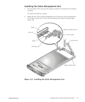
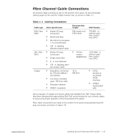
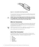
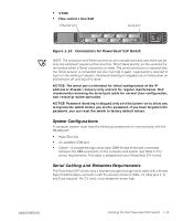
Fibre Channel Cable Connections All network cable connections are on the switch's front panel. All recommended cabling supports the switch's 1-Gbps transfer rate, as shown in Table 1-1. Table 1-1. Cabling Connections Cable type SWL Fiber Optic LWL Fiber Optic Copper Cable Specification • Duplex SC plug connectors • Multimode fiber • 50 or 62.5 micrometers (µm) core diameter • 125 µm cladding diameter duplex cable • Duplex SC plug connectors • Single mode fiber • 9 µm core diameter • 125 µm cladding diam- eter duplex cable • Impedance controlled for 150-ohm differential systems • Low skew, shielded- quad, 150-ohm cable • Polarized interface • HSSDC receptacle Maximum Run Length 500 meters (m) (1641 feet) • 10 Kilo- meters (32820 feet) 12 m (38 feet) GBIC Module 770-850 µm without open fiber control (non-OFC) 1270-1350 µm without open fiber control (non-OFC) • SCA2 printed circuit board (PCB) interface • HSSDC input/output (I/O) Various lengths of copper and optical cables are available from Dell. These cables have been designed and approved by Dell. Dell recommends the use of these cables to ensure the proper operation of the PowerVault 51F system. Fiber cable connections are made to the switch's front panel using standard dual SC plug connectors as shown in Figure 1-9. support.dell.com Installing the Dell PowerVault 51F Switch 1-13
-
 1
1 -
2
-
3
-
4
-
5
-
6
-
7
-
8
-
9
-
10
-
11
-
12
-
13
-
14
-
15
-
16
-
17
-
18
-
19
-
20
-
21
-
22
-
23
-
24
-
25
-
26
-
27
-
28
-
29
-
30
-
31
-
32
-
33
-
34
-
35
-
 36
36 -
 37
37 -
 38
38 -
 39
39 -
 40
40 -
 41
41 -
 42
42 -
 43
43 -
 44
44 -
 45
45 -
 46
46 -
47
-
48
-
49
-
50
-
51
-
52
-
53
-
54
-
55
-
56
-
57
-
58
-
59
-
60
-
61
-
62
-
63
-
64
-
65
-
66
-
67
-
68
-
69
-
70
-
71
-
72
-
73
-
74
-
75
-
76
-
77
-
78
-
79
-
80
-
81
-
82
-
83
-
84
-
85
-
86
-
87
-
88
-
89
-
90
-
91
-
92
-
93
-
94
-
95
-
96
-
97
-
98
-
99
-
100
-
101
-
102
-
103
-
104
-
105
-
106
-
107
-
108
-
109
-
110
-
111
-
112
-
113
-
114
-
115
-
116
-
117
-
118
-
119
-
120
-
121
-
122
-
123
-
124
-
125
-
126
-
127
-
128
-
129
-
130
-
131
-
132
-
133
-
134
-
135
-
136
-
137
-
138
-
139
-
140
-
141
-
142
-
143
-
144
-
145
-
146
-
147
-
148
-
149
-
150
-
151
-
152
-
153
-
154
-
155
-
156
 |
 |
