Epson Apex 200 User Manual - Page 127
Main circuit board jumper settings, main circuit board.
 |
View all Epson Apex 200 manuals
Add to My Manuals
Save this manual to your list of manuals |
Page 127 highlights
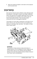
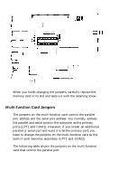
Math coprocessor clock speed. If you install an 80287 math coprocessor, you may need to set the jumpers for a different clock speed. The jumpers determine the speed of the coprocessor. Since it is easy to damage a math coprocessor, you should have your Epson Customer Care Center install it for you. In addition to checking the jumper settings, you also need to run the Setup program to change the settings in the CMOS RAM, and you may want to test the coprocessor with the System Diagnostics program. See Chapter 2 for instructions on running Setup. See Appendix C for instructions on testing the math coprocessor. The table below shows the functions for the jumpers on the main circuit board. Main circuit board jumper settings Jumper number 1 2 3 4 5 A B A A B A A B B B AA BB * Default setting Function 1 wait state for EPROM access * 2 wait states for EPROM access 1 wait state for 16-bit option card * 2 wait states for 16-bit option card 3 wait states for 16-bit option card 4 wait states for 16-bit option card * Set coprocessor clock at 8 MHz * Set coprocessor at 1/3 of CPU speed To access the main circuit board jumpers, you must remove the memory card from the computer, as described above. Do not try to access the jumpers while this card is still in the computer. The locations of jumpers J1-J5 on the main circuit board are shown in the following illustration. Refer to the table above to set them as needed. Installing Option Cards 5-11
-
 1
1 -
2
-
3
-
4
-
5
-
6
-
7
-
8
-
9
-
10
-
11
-
12
-
13
-
14
-
15
-
16
-
17
-
18
-
19
-
20
-
21
-
22
-
23
-
24
-
25
-
26
-
27
-
28
-
29
-
30
-
31
-
32
-
33
-
34
-
35
-
36
-
37
-
38
-
39
-
40
-
41
-
42
-
43
-
44
-
45
-
46
-
47
-
48
-
49
-
50
-
51
-
52
-
53
-
54
-
55
-
56
-
57
-
58
-
59
-
60
-
61
-
62
-
63
-
64
-
65
-
66
-
67
-
68
-
69
-
70
-
71
-
72
-
73
-
74
-
75
-
76
-
77
-
78
-
79
-
80
-
81
-
82
-
83
-
84
-
85
-
86
-
87
-
88
-
89
-
90
-
91
-
92
-
93
-
94
-
95
-
96
-
97
-
98
-
99
-
100
-
101
-
102
-
103
-
104
-
105
-
106
-
107
-
108
-
109
-
110
-
111
-
112
-
113
-
114
-
115
-
116
-
117
-
118
-
119
-
120
-
121
-
 122
122 -
 123
123 -
 124
124 -
 125
125 -
 126
126 -
 127
127 -
 128
128 -
 129
129 -
 130
130 -
 131
131 -
 132
132 -
133
-
134
-
135
-
136
-
137
-
138
-
139
-
140
-
141
-
142
-
143
-
144
-
145
-
146
-
147
-
148
-
149
-
150
-
151
-
152
-
153
-
154
-
155
-
156
-
157
-
158
-
159
-
160
-
161
-
162
-
163
-
164
-
165
-
166
-
167
-
168
-
169
-
170
-
171
-
172
-
173
-
174
-
175
-
176
-
177
-
178
-
179
-
180
-
181
-
182
-
183
-
184
-
185
-
186
-
187
-
188
-
189
-
190
-
191
-
192
-
193
-
194
-
195
-
196
-
197
-
198
-
199
-
200
-
201
-
202
-
203
-
204
-
205
-
206
-
207
-
208
-
209
-
210
-
211
-
212
-
213
-
214
-
215
-
216
-
217
-
218
-
219
-
220
-
221
-
222
-
223
-
224
-
225
-
226
-
227
-
228
-
229
-
230
-
231
-
232
-
233
-
234
-
235
-
236
-
237
-
238
-
239
-
240
-
241
-
242
-
243
-
244
-
245
-
246
-
247
-
248
-
249
-
250
-
251
 |
 |
