Sharp MX-M700 MX-M550 MX-M620 MX-M700 Operation Manual - Page 23
Interior - drum
 |
View all Sharp MX-M700 manuals
Add to My Manuals
Save this manual to your list of manuals |
Page 23 highlights
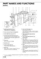
Interior PART NAMES AND FUNCTIONS 1 15 Duplex unit Open this cover to remove a misfeed from the fusing unit area. 16 Fusing unit Toner images are fused here. CAUTION The fusing unit is hot. Take care in removing misfed paper. 17 Cover of the duplex unit Open when a misfeed has occurred in duplex unit. 18 Toner cartridge*2 This holds toner for printing. The toner cartridge must be replaced when indicated on the operation panel. 19 Main power switch (See page 1-17) Keep this switch turned on when the fax option or Internet fax option is installed. 20 Right side cover Open when a misfeed has occurred in the bypass tray or large capacity tray. 21 Upper cover of large capacity tray Open when a misfeed has occurred in the large capacity tray. 22 Left side cover release Push this knob up to open the left side cover. 23 Left cover of paper drawer Open this cover to remove paper misfed in tray 3 or tray 4. 24 Photoconductive drum Images are formed on the photoconductive drum. NOTE Do not touch or damage the photoconductive drum. *2 See page 2-21 for the procedure for installing and replacing the toner cartridge. 1-11
-
 1
1 -
2
-
3
-
4
-
5
-
6
-
7
-
8
-
9
-
10
-
11
-
12
-
13
-
14
-
15
-
16
-
17
-
 18
18 -
 19
19 -
 20
20 -
 21
21 -
 22
22 -
 23
23 -
 24
24 -
 25
25 -
 26
26 -
 27
27 -
 28
28 -
29
-
30
-
31
-
32
-
33
-
34
-
35
-
36
-
37
-
38
-
39
-
40
-
41
-
42
-
43
-
44
-
45
-
46
-
47
-
48
-
49
-
50
-
51
-
52
-
53
-
54
-
55
-
56
-
57
-
58
-
59
-
60
-
61
-
62
-
63
-
64
-
65
-
66
-
67
-
68
-
69
-
70
-
71
-
72
-
73
-
74
-
75
-
76
-
77
-
78
-
79
-
80
-
81
-
82
-
83
-
84
-
85
-
86
-
87
-
88
-
89
-
90
-
91
-
92
-
93
-
94
-
95
-
96
-
97
-
98
-
99
-
100
-
101
-
102
-
103
-
104
-
105
-
106
-
107
-
108
-
109
-
110
-
111
-
112
-
113
-
114
-
115
-
116
-
117
-
118
-
119
-
120
-
121
-
122
-
123
-
124
-
125
-
126
-
127
-
128
-
129
-
130
-
131
-
132
-
133
-
134
-
135
-
136
-
137
-
138
-
139
-
140
-
141
-
142
-
143
-
144
-
145
-
146
-
147
-
148
-
149
-
150
-
151
-
152
-
153
-
154
-
155
-
156
-
157
-
158
-
159
-
160
-
161
-
162
-
163
-
164
-
165
-
166
-
167
-
168
-
169
-
170
-
171
-
172
-
173
-
174
-
175
-
176
-
177
-
178
-
179
-
180
-
181
-
182
-
183
-
184
-
185
-
186
-
187
-
188
-
189
-
190
-
191
-
192
-
193
-
194
-
195
-
196
-
197
-
198
-
199
-
200
 |
 |
