Toshiba Portege M100 Maintenance Manual - Page 215
Disassembly Procedures, Replacement Procedures, General
 |
View all Toshiba Portege M100 manuals
Add to My Manuals
Save this manual to your list of manuals |
Page 215 highlights
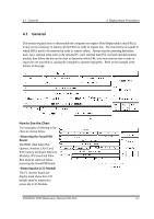
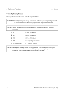
4 Replacement Procedures 4.1 General Disassembly Procedures The computer has two basic types of cable connectors: q Pressure Plate Connectors q Normal Pin Connectors To disconnect a Pressure Plate connector, lift up the tabs on either side of the connector's plastic pressure plate and slide the cable out of the connector. To connect the cable to a Pressure Plate connector, make sure the pressure plate is fully lifted and slide the cable into the connector. Secure the cable in place by pushing the sides of the pressure plate down so the plate is flush with the sides of the connector. Gently pull on the cable to make sure the cable is secure. If you pull out the connector, connect it again making sure the connector's pressure plate is fully lifted when you insert the cable. Standard pin connectors are used with all other cables. These connectors can be connected and disconnected by simply pulling them apart or pushing them together. Assembly Procedures After you have disassembled the computer and fixed or repaired the problem that was causing the computer to operate abnormally, you will need to reassemble the computer. Install all the removed FRUs following the steps described in the corresponding sections in this chapter. While assembling the computer, remember the following general points: q Take your time, making sure you follow the instructions closely. Most problems arise when you get in a hurry assembling the computer. q Make sure all cables and connectors are securely fastened. q Before securing the FRU or other parts, make sure that no cables will be pinched by screws or the FRU. q Check that all latches are closed securely in place. q Make sure all the correct screws are used to secure all FRUs. Using the wrong screw can either damage the threads on the screw or the head of the screw and may prevent proper seating of an FRU. After installing an FRU in the computer, confirm that the FRU and the computer are functioning properly. 4-4 PORTEGE M100 Maintenance Manual (960-452)
-
 1
1 -
2
-
3
-
4
-
5
-
6
-
7
-
8
-
9
-
10
-
11
-
12
-
13
-
14
-
15
-
16
-
17
-
18
-
19
-
20
-
21
-
22
-
23
-
24
-
25
-
26
-
27
-
28
-
29
-
30
-
31
-
32
-
33
-
34
-
35
-
36
-
37
-
38
-
39
-
40
-
41
-
42
-
43
-
44
-
45
-
46
-
47
-
48
-
49
-
50
-
51
-
52
-
53
-
54
-
55
-
56
-
57
-
58
-
59
-
60
-
61
-
62
-
63
-
64
-
65
-
66
-
67
-
68
-
69
-
70
-
71
-
72
-
73
-
74
-
75
-
76
-
77
-
78
-
79
-
80
-
81
-
82
-
83
-
84
-
85
-
86
-
87
-
88
-
89
-
90
-
91
-
92
-
93
-
94
-
95
-
96
-
97
-
98
-
99
-
100
-
101
-
102
-
103
-
104
-
105
-
106
-
107
-
108
-
109
-
110
-
111
-
112
-
113
-
114
-
115
-
116
-
117
-
118
-
119
-
120
-
121
-
122
-
123
-
124
-
125
-
126
-
127
-
128
-
129
-
130
-
131
-
132
-
133
-
134
-
135
-
136
-
137
-
138
-
139
-
140
-
141
-
142
-
143
-
144
-
145
-
146
-
147
-
148
-
149
-
150
-
151
-
152
-
153
-
154
-
155
-
156
-
157
-
158
-
159
-
160
-
161
-
162
-
163
-
164
-
165
-
166
-
167
-
168
-
169
-
170
-
171
-
172
-
173
-
174
-
175
-
176
-
177
-
178
-
179
-
180
-
181
-
182
-
183
-
184
-
185
-
186
-
187
-
188
-
189
-
190
-
191
-
192
-
193
-
194
-
195
-
196
-
197
-
198
-
199
-
200
-
201
-
202
-
203
-
204
-
205
-
206
-
207
-
208
-
209
-
 210
210 -
 211
211 -
 212
212 -
 213
213 -
 214
214 -
 215
215 -
 216
216 -
 217
217 -
 218
218 -
 219
219 -
 220
220 -
221
-
222
-
223
-
224
-
225
-
226
-
227
-
228
-
229
-
230
-
231
-
232
-
233
-
234
-
235
-
236
-
237
-
238
-
239
-
240
-
241
-
242
-
243
-
244
-
245
-
246
-
247
-
248
-
249
-
250
-
251
-
252
-
253
-
254
-
255
-
256
-
257
-
258
-
259
-
260
-
261
-
262
-
263
-
264
-
265
-
266
-
267
-
268
-
269
-
270
-
271
-
272
-
273
-
274
-
275
-
276
-
277
-
278
-
279
-
280
-
281
-
282
-
283
-
284
-
285
-
286
-
287
-
288
-
289
-
290
-
291
-
292
-
293
-
294
-
295
-
296
-
297
-
298
-
299
-
300
-
301
-
302
-
303
-
304
-
305
-
306
-
307
-
308
-
309
-
310
-
311
-
312
-
313
-
314
-
315
-
316
-
317
-
318
-
319
-
320
-
321
-
322
-
323
-
324
-
325
-
326
-
327
-
328
-
329
-
330
-
331
-
332
-
333
-
334
-
335
-
336
-
337
-
338
-
339
-
340
-
341
-
342
-
343
-
344
-
345
-
346
-
347
-
348
-
349
-
350
-
351
-
352
-
353
-
354
-
355
-
356
-
357
-
358
-
359
-
360
-
361
-
362
-
363
-
364
-
365
-
366
-
367
-
368
-
369
-
370
-
371
-
372
-
373
-
374
-
375
-
376
-
377
-
378
-
379
-
380
-
381
-
382
-
383
-
384
-
385
-
386
 |
 |