Toshiba Portege M100 Maintenance Manual - Page 298
TFT FL (Model 12.1 Toshiba), Replacement Procedures, TFT FL, Do not damage the FPC.,
 |
View all Toshiba Portege M100 manuals
Add to My Manuals
Save this manual to your list of manuals |
Page 298 highlights
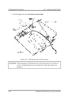
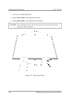
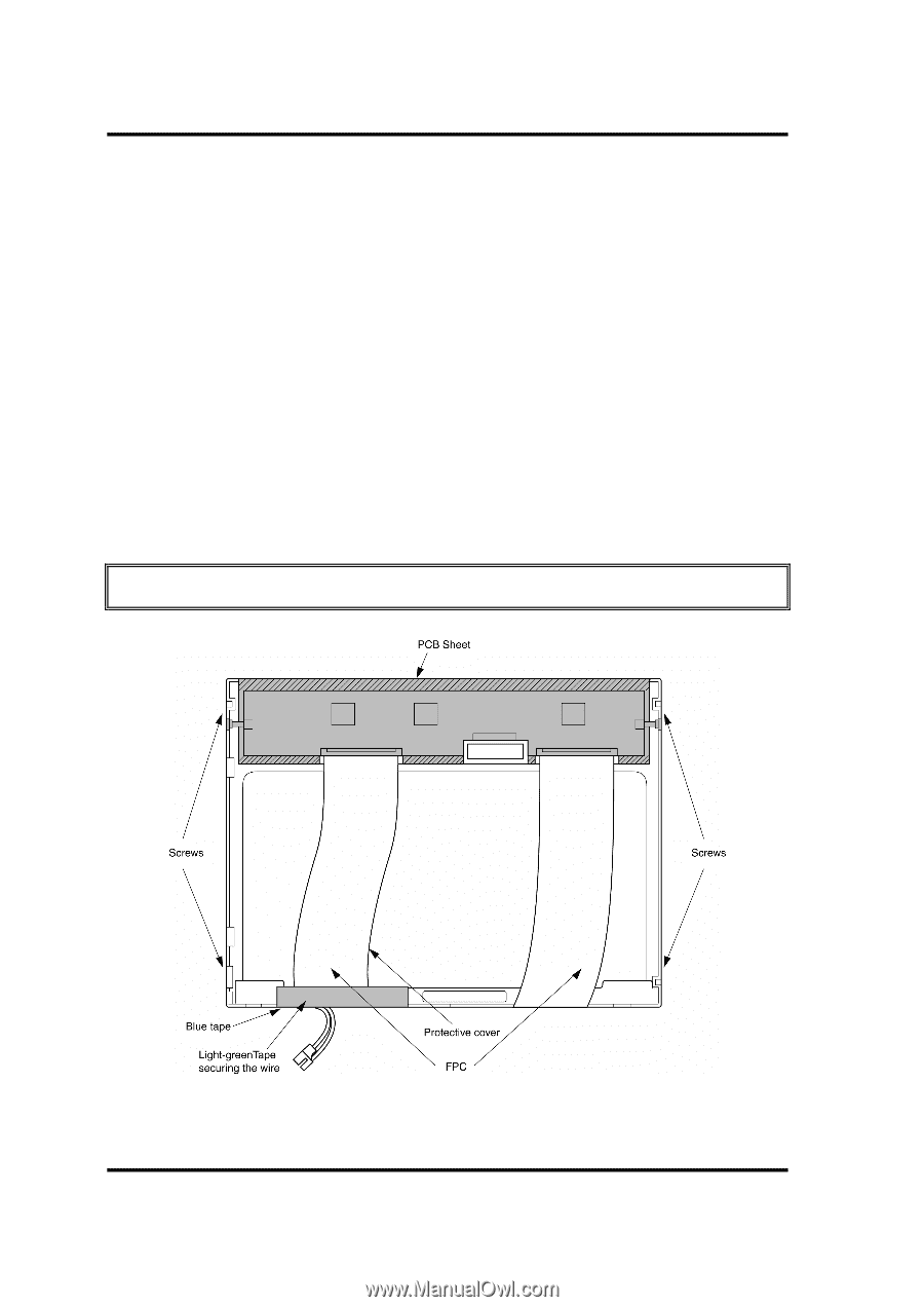
4 Replacement Procedures 4.23 TFT FL 4.23 TFT FL (Model 12.1 Toshiba) Removing the TFT FL (Model 12.1 Toshiba) To remove the TFT FL (Model 12.1 Toshiba), follow the steps below and refer to Figures 4-55 to 4-58. 1. Carefully, turn the LCD module upside down on the flat surface of the table. To avoid damaging the surface of the LCD module, lay it on a protective, dust-free sheet such as a soft, clean cloth. 2. Remove the light-green tape securing the wire. 3. Remove the FPC protective sheet, the blue tape and the PCB sheet. Keep the PCB sheet for reuse. 4. Remove four screws. CAUTION: Do not damage the FPC. Figure 4-55 Removing the tapes and sheet 4-82 PORTEGE M100 Maintenance Manual (960-452)
-
 1
1 -
2
-
3
-
4
-
5
-
6
-
7
-
8
-
9
-
10
-
11
-
12
-
13
-
14
-
15
-
16
-
17
-
18
-
19
-
20
-
21
-
22
-
23
-
24
-
25
-
26
-
27
-
28
-
29
-
30
-
31
-
32
-
33
-
34
-
35
-
36
-
37
-
38
-
39
-
40
-
41
-
42
-
43
-
44
-
45
-
46
-
47
-
48
-
49
-
50
-
51
-
52
-
53
-
54
-
55
-
56
-
57
-
58
-
59
-
60
-
61
-
62
-
63
-
64
-
65
-
66
-
67
-
68
-
69
-
70
-
71
-
72
-
73
-
74
-
75
-
76
-
77
-
78
-
79
-
80
-
81
-
82
-
83
-
84
-
85
-
86
-
87
-
88
-
89
-
90
-
91
-
92
-
93
-
94
-
95
-
96
-
97
-
98
-
99
-
100
-
101
-
102
-
103
-
104
-
105
-
106
-
107
-
108
-
109
-
110
-
111
-
112
-
113
-
114
-
115
-
116
-
117
-
118
-
119
-
120
-
121
-
122
-
123
-
124
-
125
-
126
-
127
-
128
-
129
-
130
-
131
-
132
-
133
-
134
-
135
-
136
-
137
-
138
-
139
-
140
-
141
-
142
-
143
-
144
-
145
-
146
-
147
-
148
-
149
-
150
-
151
-
152
-
153
-
154
-
155
-
156
-
157
-
158
-
159
-
160
-
161
-
162
-
163
-
164
-
165
-
166
-
167
-
168
-
169
-
170
-
171
-
172
-
173
-
174
-
175
-
176
-
177
-
178
-
179
-
180
-
181
-
182
-
183
-
184
-
185
-
186
-
187
-
188
-
189
-
190
-
191
-
192
-
193
-
194
-
195
-
196
-
197
-
198
-
199
-
200
-
201
-
202
-
203
-
204
-
205
-
206
-
207
-
208
-
209
-
210
-
211
-
212
-
213
-
214
-
215
-
216
-
217
-
218
-
219
-
220
-
221
-
222
-
223
-
224
-
225
-
226
-
227
-
228
-
229
-
230
-
231
-
232
-
233
-
234
-
235
-
236
-
237
-
238
-
239
-
240
-
241
-
242
-
243
-
244
-
245
-
246
-
247
-
248
-
249
-
250
-
251
-
252
-
253
-
254
-
255
-
256
-
257
-
258
-
259
-
260
-
261
-
262
-
263
-
264
-
265
-
266
-
267
-
268
-
269
-
270
-
271
-
272
-
273
-
274
-
275
-
276
-
277
-
278
-
279
-
280
-
281
-
282
-
283
-
284
-
285
-
286
-
287
-
288
-
289
-
290
-
291
-
292
-
 293
293 -
 294
294 -
 295
295 -
 296
296 -
 297
297 -
 298
298 -
 299
299 -
 300
300 -
 301
301 -
 302
302 -
 303
303 -
304
-
305
-
306
-
307
-
308
-
309
-
310
-
311
-
312
-
313
-
314
-
315
-
316
-
317
-
318
-
319
-
320
-
321
-
322
-
323
-
324
-
325
-
326
-
327
-
328
-
329
-
330
-
331
-
332
-
333
-
334
-
335
-
336
-
337
-
338
-
339
-
340
-
341
-
342
-
343
-
344
-
345
-
346
-
347
-
348
-
349
-
350
-
351
-
352
-
353
-
354
-
355
-
356
-
357
-
358
-
359
-
360
-
361
-
362
-
363
-
364
-
365
-
366
-
367
-
368
-
369
-
370
-
371
-
372
-
373
-
374
-
375
-
376
-
377
-
378
-
379
-
380
-
381
-
382
-
383
-
384
-
385
-
386
 |
 |
4
Replacement Procedures
4.23
TFT FL
4-82
PORTEGE M100 Maintenance Manual (960-452)
4.23 TFT FL (Model 12.1 Toshiba)
Removing the TFT FL (Model 12.1 Toshiba)
To remove the TFT FL (Model 12.1 Toshiba), follow the steps below and refer to Figures
4-55 to 4-58.
1.
Carefully, turn the LCD module upside down on the flat surface of the table. To avoid
damaging the surface of the LCD module, lay it on a protective, dust-free sheet such as a
soft, clean cloth.
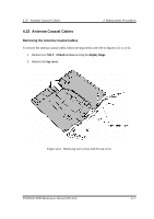
2.
Remove the light-green tape securing the wire.
3.
Remove the FPC protective sheet, the blue tape and the PCB sheet. Keep the PCB sheet
for reuse.
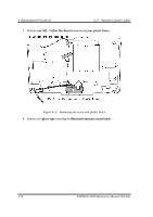
4.
Remove four screws.
CAUTION:
Do not damage the FPC.
Figure 4-55
Removing the tapes and sheet