Brother International HL-3400CN Service Manual - Page 117
Dvlm/dvlc
 |
UPC - 012502526223
View all Brother International HL-3400CN manuals
Add to My Manuals
Save this manual to your list of manuals |
Page 117 highlights
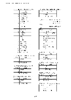
CHAPTER 4 STRUCTURE OF SYSTEM COMPONENTS (1) Symbol and Parts Name Symbol Parts Name LVPS Low-voltage power supply unit DSW1 Interlock switch (Front) DSW2 Interlock switch (Top) DSW3 Interlock switch (Back) FUSER Unit Fusing unit TH Thermistor HR Heat roller BR Back-up roller TFU1 / TFU2 Thermal fuse HVU High-voltage power supply unit MCTL MCTL PWB PANEL Panel PWB LCD LCD PWB Laser Unit Laser unit (Optical unit) SCM Scanner motor PDU PDL PCB LDU LDU PCB M M Main motor DM Developer drive motor FUFAN (EX) fuser fan motor CTFAN (PS) Control fan motor OZFAN (OZ) Ozone fan motor DVLK/DVLY/ Developer clutch (K.Y.M.C) DVLM/DVLC FUCL Fuser clutch FBCL Cleaning clutch Symbol Parts Name 1OO1 1OO1 PWB OHP OHP sensor PEU (PS3) Paper empty sensor PT1 (PS1) Paper feeding sensor EN (PS4) Drum encoder sensor Erase Lamp Erase lamp TDP / TTR Toner sensor TNK Toner key sensor PSU Paper size sensor PFUL (PS6) Paper full sensor CSR (PS5) Cleaning roller sensor PT2 (PS2) Paper exit sensor DPJ Drum jam sensor OIL Oil sensor BPS Belt sensor TBLE / TBFL Waste toner sensor 1OO2 IOD2 PWB 1OO3 1OO3 PWB FBCM Cleaning cam clutch TRCM TR cam clutch LFU Lower tray unit PCLU Paper feeding clutch PSL(MC) / Developer cam clutch PSL (KY) RECL Registration clutch 4-66
-
 1
1 -
2
-
3
-
4
-
5
-
6
-
7
-
8
-
9
-
10
-
11
-
12
-
13
-
14
-
15
-
16
-
17
-
18
-
19
-
20
-
21
-
22
-
23
-
24
-
25
-
26
-
27
-
28
-
29
-
30
-
31
-
32
-
33
-
34
-
35
-
36
-
37
-
38
-
39
-
40
-
41
-
42
-
43
-
44
-
45
-
46
-
47
-
48
-
49
-
50
-
51
-
52
-
53
-
54
-
55
-
56
-
57
-
58
-
59
-
60
-
61
-
62
-
63
-
64
-
65
-
66
-
67
-
68
-
69
-
70
-
71
-
72
-
73
-
74
-
75
-
76
-
77
-
78
-
79
-
80
-
81
-
82
-
83
-
84
-
85
-
86
-
87
-
88
-
89
-
90
-
91
-
92
-
93
-
94
-
95
-
96
-
97
-
98
-
99
-
100
-
101
-
102
-
103
-
104
-
105
-
106
-
107
-
108
-
109
-
110
-
111
-
 112
112 -
 113
113 -
 114
114 -
 115
115 -
 116
116 -
 117
117 -
 118
118 -
 119
119 -
 120
120 -
 121
121 -
 122
122 -
123
-
124
-
125
-
126
-
127
-
128
-
129
-
130
-
131
-
132
-
133
-
134
-
135
-
136
-
137
-
138
-
139
-
140
-
141
-
142
-
143
-
144
-
145
-
146
-
147
-
148
-
149
-
150
-
151
-
152
-
153
-
154
-
155
-
156
-
157
-
158
-
159
-
160
-
161
-
162
-
163
-
164
-
165
-
166
-
167
-
168
-
169
-
170
-
171
-
172
-
173
-
174
-
175
-
176
-
177
-
178
-
179
-
180
-
181
-
182
-
183
-
184
-
185
-
186
-
187
-
188
-
189
-
190
-
191
-
192
-
193
-
194
-
195
-
196
-
197
-
198
-
199
-
200
-
201
-
202
-
203
-
204
-
205
-
206
-
207
-
208
-
209
-
210
-
211
-
212
-
213
-
214
-
215
-
216
-
217
-
218
-
219
-
220
-
221
-
222
-
223
-
224
-
225
-
226
-
227
-
228
-
229
-
230
-
231
-
232
-
233
-
234
-
235
-
236
-
237
-
238
-
239
-
240
-
241
-
242
-
243
-
244
-
245
-
246
-
247
-
248
-
249
-
250
-
251
-
252
-
253
-
254
-
255
-
256
-
257
-
258
-
259
-
260
-
261
-
262
-
263
-
264
-
265
-
266
-
267
-
268
-
269
-
270
-
271
-
272
-
273
-
274
-
275
-
276
-
277
-
278
-
279
-
280
-
281
-
282
-
283
-
284
-
285
-
286
-
287
-
288
-
289
-
290
-
291
-
292
-
293
-
294
-
295
-
296
-
297
-
298
-
299
-
300
-
301
-
302
-
303
-
304
-
305
-
306
-
307
-
308
-
309
-
310
-
311
-
312
-
313
-
314
-
315
-
316
-
317
-
318
-
319
-
320
-
321
-
322
-
323
-
324
-
325
-
326
-
327
-
328
-
329
-
330
-
331
-
332
-
333
-
334
-
335
-
336
-
337
-
338
-
339
-
340
-
341
-
342
-
343
-
344
-
345
-
346
-
347
 |
 |
