Brother International HL-3400CN Service Manual - Page 236
disassembly.
 |
UPC - 012502526223
View all Brother International HL-3400CN manuals
Add to My Manuals
Save this manual to your list of manuals |
Page 236 highlights
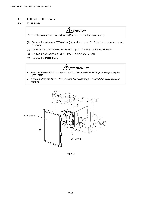
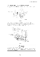
CHAPTER 7 DISASSEMBLY & RE-ASSEMBLY 4.3 Left Side of the Printer 4.3.1 MCTL PWB A CAUTION Remove the Main (Video Controller) PWB before starting this disassembly. (1) Remove the set screw ST3x6 (1 pc.) from shield cover 'B'. Slide the cover upwards and remove it (2) Disconnect all the harness connectors (7 pcs.) connected to the MCTL PWB. (3) Remove the set screws ST3x6 (4 pcs.) from the MCTL PWB. (4) Remove the MCTL PWB. APRECAUTION • Read the internal RAM counter information from the MCTL PWB prior to replacing the MCTL PWB. • When handling the MCTL PWB, ensure that no damage is caused due to electrostatic charges. ____------ -,, ----- Shield cover 'B' 1 dz. 76.-------Z MCTL PWB .....r,„ Fig. 7-45 7-32
-
 1
1 -
2
-
3
-
4
-
5
-
6
-
7
-
8
-
9
-
10
-
11
-
12
-
13
-
14
-
15
-
16
-
17
-
18
-
19
-
20
-
21
-
22
-
23
-
24
-
25
-
26
-
27
-
28
-
29
-
30
-
31
-
32
-
33
-
34
-
35
-
36
-
37
-
38
-
39
-
40
-
41
-
42
-
43
-
44
-
45
-
46
-
47
-
48
-
49
-
50
-
51
-
52
-
53
-
54
-
55
-
56
-
57
-
58
-
59
-
60
-
61
-
62
-
63
-
64
-
65
-
66
-
67
-
68
-
69
-
70
-
71
-
72
-
73
-
74
-
75
-
76
-
77
-
78
-
79
-
80
-
81
-
82
-
83
-
84
-
85
-
86
-
87
-
88
-
89
-
90
-
91
-
92
-
93
-
94
-
95
-
96
-
97
-
98
-
99
-
100
-
101
-
102
-
103
-
104
-
105
-
106
-
107
-
108
-
109
-
110
-
111
-
112
-
113
-
114
-
115
-
116
-
117
-
118
-
119
-
120
-
121
-
122
-
123
-
124
-
125
-
126
-
127
-
128
-
129
-
130
-
131
-
132
-
133
-
134
-
135
-
136
-
137
-
138
-
139
-
140
-
141
-
142
-
143
-
144
-
145
-
146
-
147
-
148
-
149
-
150
-
151
-
152
-
153
-
154
-
155
-
156
-
157
-
158
-
159
-
160
-
161
-
162
-
163
-
164
-
165
-
166
-
167
-
168
-
169
-
170
-
171
-
172
-
173
-
174
-
175
-
176
-
177
-
178
-
179
-
180
-
181
-
182
-
183
-
184
-
185
-
186
-
187
-
188
-
189
-
190
-
191
-
192
-
193
-
194
-
195
-
196
-
197
-
198
-
199
-
200
-
201
-
202
-
203
-
204
-
205
-
206
-
207
-
208
-
209
-
210
-
211
-
212
-
213
-
214
-
215
-
216
-
217
-
218
-
219
-
220
-
221
-
222
-
223
-
224
-
225
-
226
-
227
-
228
-
229
-
230
-
 231
231 -
 232
232 -
 233
233 -
 234
234 -
 235
235 -
 236
236 -
 237
237 -
 238
238 -
 239
239 -
 240
240 -
 241
241 -
242
-
243
-
244
-
245
-
246
-
247
-
248
-
249
-
250
-
251
-
252
-
253
-
254
-
255
-
256
-
257
-
258
-
259
-
260
-
261
-
262
-
263
-
264
-
265
-
266
-
267
-
268
-
269
-
270
-
271
-
272
-
273
-
274
-
275
-
276
-
277
-
278
-
279
-
280
-
281
-
282
-
283
-
284
-
285
-
286
-
287
-
288
-
289
-
290
-
291
-
292
-
293
-
294
-
295
-
296
-
297
-
298
-
299
-
300
-
301
-
302
-
303
-
304
-
305
-
306
-
307
-
308
-
309
-
310
-
311
-
312
-
313
-
314
-
315
-
316
-
317
-
318
-
319
-
320
-
321
-
322
-
323
-
324
-
325
-
326
-
327
-
328
-
329
-
330
-
331
-
332
-
333
-
334
-
335
-
336
-
337
-
338
-
339
-
340
-
341
-
342
-
343
-
344
-
345
-
346
-
347
 |
 |

CHAPTER
7
DISASSEMBLY
&
RE
-ASSEMBLY
4.3
Left
Side
of
the
Printer
4.3.1
MCTL
PWB
A
CAUTION
Remove
the
Main
(Video
Controller)
PWB
before
starting
this
disassembly.
(1)
Remove
the
set
screw
ST3x6
(1
pc.)
from
shield
cover
'B'.
Slide
the
cover
upwards
and
remove
it
(2)
Disconnect
all
the
harness
connectors
(7
pcs.)
connected
to
the
MCTL
PWB.
(3)
Remove
the
set
screws
ST3x6
(4
pcs.)
from
the
MCTL
PWB.
(4)
Remove
the
MCTL
PWB.
A
PRECAUTION
•
Read
the
internal
RAM
counter
information
from
the
MCTL
PWB
prior
to
replacing
the
MCTL
PWB.
•
When
handling
the
MCTL
PWB,
ensure
that
no
damage
is
caused
due
to
electrostatic
charges.
Shield
cover
'B'
____------
1
d
z.
MCTL
PWB
Fig.
7-45
-,,
-----
76.-
--
---Z
--
.....
r,„
7-32