Brother International HL-3400CN Service Manual - Page 4
Structure, System Components, Control, Panel, Operation
 |
UPC - 012502526223
View all Brother International HL-3400CN manuals
Add to My Manuals
Save this manual to your list of manuals |
Page 4 highlights
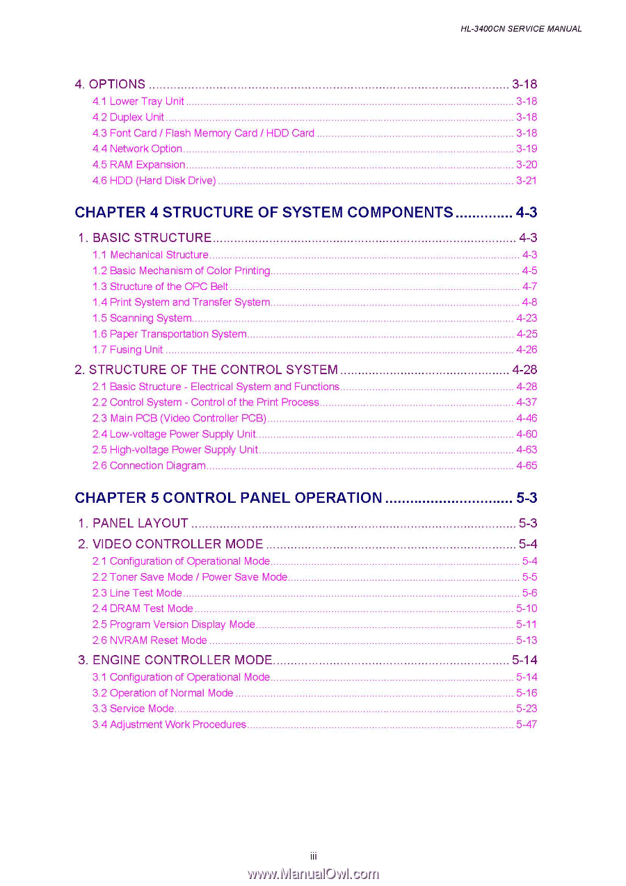
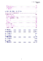
HL-3400CN SERVICE MANUAL 4. OPTIONS 4.1 Lower Tray Unit 4.2 Duplex Unit 4.3 Font Card / Flash Memory Card / HDD Card 4.4 Network Option 4.5 RAM Expansion 4.6 HDD (Hard Disk Drive) CHAPTER 4 STRUCTURE OF SYSTEM COMPONENTS 1. BASIC STRUCTURE 1.1 Mechanical Structure 1.2 Basic Mechanism of Color Printing 1.3 Structure of the OPC Belt 1.4 Print System and Transfer System 1.5 Scanning System 1.6 Paper Transportation System. 1.7 Fusing Unit 2. STRUCTURE OF THE CONTROL SYSTEM 2.1 Basic Structure - Electrical System and Functions 2.2 Control System - Control of the Print Process 2.3 Main PCB (Video Controller PCB) 2.4 Low-voltage Power Supply Unit 2.5 High-voltage Power Supply Unit 2.6 Connection Diagram CHAPTER 5 CONTROL PANEL OPERATION 1. PANEL LAYOUT 2. VIDEO CONTROLLER MODE 2.1 Configuration of Operational Mode 2.2 Toner Save Mode / Power Save Mode 2.3 Line Test Mode 2.4 DRAM Test Mode 2.5 Program Version Display Mode 2.6 NVRAM Reset Mode 3. ENGINE CONTROLLER MODE 3.1 Configuration of Operational Mode 3.2 Operation of Normal Mode 3.3 Service Mode. 3.4 Adjustment Work Procedures 3-18 3-18 3-18 3-18 3-19 3-20 3-21 4-3 4-3 4-3 4-5 4-7 4-8 4-23 4-25 4-26 4-28 4-28 4-37 4-46 4-60 4-63 4-65 5-3 5-3 5-4 5-4 5-5 5-6 5-10 5-11 5-13 5-14 5-14 5-16 5-23 5-47 III
-
 1
1 -
 2
2 -
 3
3 -
 4
4 -
 5
5 -
 6
6 -
 7
7 -
 8
8 -
 9
9 -
 10
10 -
11
-
12
-
13
-
14
-
15
-
16
-
17
-
18
-
19
-
20
-
21
-
22
-
23
-
24
-
25
-
26
-
27
-
28
-
29
-
30
-
31
-
32
-
33
-
34
-
35
-
36
-
37
-
38
-
39
-
40
-
41
-
42
-
43
-
44
-
45
-
46
-
47
-
48
-
49
-
50
-
51
-
52
-
53
-
54
-
55
-
56
-
57
-
58
-
59
-
60
-
61
-
62
-
63
-
64
-
65
-
66
-
67
-
68
-
69
-
70
-
71
-
72
-
73
-
74
-
75
-
76
-
77
-
78
-
79
-
80
-
81
-
82
-
83
-
84
-
85
-
86
-
87
-
88
-
89
-
90
-
91
-
92
-
93
-
94
-
95
-
96
-
97
-
98
-
99
-
100
-
101
-
102
-
103
-
104
-
105
-
106
-
107
-
108
-
109
-
110
-
111
-
112
-
113
-
114
-
115
-
116
-
117
-
118
-
119
-
120
-
121
-
122
-
123
-
124
-
125
-
126
-
127
-
128
-
129
-
130
-
131
-
132
-
133
-
134
-
135
-
136
-
137
-
138
-
139
-
140
-
141
-
142
-
143
-
144
-
145
-
146
-
147
-
148
-
149
-
150
-
151
-
152
-
153
-
154
-
155
-
156
-
157
-
158
-
159
-
160
-
161
-
162
-
163
-
164
-
165
-
166
-
167
-
168
-
169
-
170
-
171
-
172
-
173
-
174
-
175
-
176
-
177
-
178
-
179
-
180
-
181
-
182
-
183
-
184
-
185
-
186
-
187
-
188
-
189
-
190
-
191
-
192
-
193
-
194
-
195
-
196
-
197
-
198
-
199
-
200
-
201
-
202
-
203
-
204
-
205
-
206
-
207
-
208
-
209
-
210
-
211
-
212
-
213
-
214
-
215
-
216
-
217
-
218
-
219
-
220
-
221
-
222
-
223
-
224
-
225
-
226
-
227
-
228
-
229
-
230
-
231
-
232
-
233
-
234
-
235
-
236
-
237
-
238
-
239
-
240
-
241
-
242
-
243
-
244
-
245
-
246
-
247
-
248
-
249
-
250
-
251
-
252
-
253
-
254
-
255
-
256
-
257
-
258
-
259
-
260
-
261
-
262
-
263
-
264
-
265
-
266
-
267
-
268
-
269
-
270
-
271
-
272
-
273
-
274
-
275
-
276
-
277
-
278
-
279
-
280
-
281
-
282
-
283
-
284
-
285
-
286
-
287
-
288
-
289
-
290
-
291
-
292
-
293
-
294
-
295
-
296
-
297
-
298
-
299
-
300
-
301
-
302
-
303
-
304
-
305
-
306
-
307
-
308
-
309
-
310
-
311
-
312
-
313
-
314
-
315
-
316
-
317
-
318
-
319
-
320
-
321
-
322
-
323
-
324
-
325
-
326
-
327
-
328
-
329
-
330
-
331
-
332
-
333
-
334
-
335
-
336
-
337
-
338
-
339
-
340
-
341
-
342
-
343
-
344
-
345
-
346
-
347
 |
 |