Brother International HL-3400CN Service Manual - Page 240
cover, Remove, screw, BT4x10, voltage, power, supply, switch, pulling, forwards., screws, ST3x6,
 |
UPC - 012502526223
View all Brother International HL-3400CN manuals
Add to My Manuals
Save this manual to your list of manuals |
Page 240 highlights
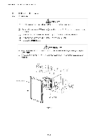
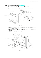
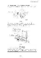
CHAPTER 7 DISASSEMBLY & RE-ASSEMBLY 4.3.6 Rear cover 3 (R) (1) Remove the set screw BT4x10 (1 pc.) of rear cover 3 (R). (2) Remove the rear cover 3 (R). CD Rear cover 3 (R) Fig. 7-51 4.3.7 Low-voltage power supply unit ( (1) Remove the power switch key by pulling it forwards. (2) Remove the set screws ST3x6 (3 pcs.) to remove the front shield. (3) Remove the set screws ST3x6 (2 pcs.) to remove the bottom shield plate. or Bottom shield plate Fig. 7-52 Front shield r \ Spring Power switch key 7-36
-
 1
1 -
2
-
3
-
4
-
5
-
6
-
7
-
8
-
9
-
10
-
11
-
12
-
13
-
14
-
15
-
16
-
17
-
18
-
19
-
20
-
21
-
22
-
23
-
24
-
25
-
26
-
27
-
28
-
29
-
30
-
31
-
32
-
33
-
34
-
35
-
36
-
37
-
38
-
39
-
40
-
41
-
42
-
43
-
44
-
45
-
46
-
47
-
48
-
49
-
50
-
51
-
52
-
53
-
54
-
55
-
56
-
57
-
58
-
59
-
60
-
61
-
62
-
63
-
64
-
65
-
66
-
67
-
68
-
69
-
70
-
71
-
72
-
73
-
74
-
75
-
76
-
77
-
78
-
79
-
80
-
81
-
82
-
83
-
84
-
85
-
86
-
87
-
88
-
89
-
90
-
91
-
92
-
93
-
94
-
95
-
96
-
97
-
98
-
99
-
100
-
101
-
102
-
103
-
104
-
105
-
106
-
107
-
108
-
109
-
110
-
111
-
112
-
113
-
114
-
115
-
116
-
117
-
118
-
119
-
120
-
121
-
122
-
123
-
124
-
125
-
126
-
127
-
128
-
129
-
130
-
131
-
132
-
133
-
134
-
135
-
136
-
137
-
138
-
139
-
140
-
141
-
142
-
143
-
144
-
145
-
146
-
147
-
148
-
149
-
150
-
151
-
152
-
153
-
154
-
155
-
156
-
157
-
158
-
159
-
160
-
161
-
162
-
163
-
164
-
165
-
166
-
167
-
168
-
169
-
170
-
171
-
172
-
173
-
174
-
175
-
176
-
177
-
178
-
179
-
180
-
181
-
182
-
183
-
184
-
185
-
186
-
187
-
188
-
189
-
190
-
191
-
192
-
193
-
194
-
195
-
196
-
197
-
198
-
199
-
200
-
201
-
202
-
203
-
204
-
205
-
206
-
207
-
208
-
209
-
210
-
211
-
212
-
213
-
214
-
215
-
216
-
217
-
218
-
219
-
220
-
221
-
222
-
223
-
224
-
225
-
226
-
227
-
228
-
229
-
230
-
231
-
232
-
233
-
234
-
 235
235 -
 236
236 -
 237
237 -
 238
238 -
 239
239 -
 240
240 -
 241
241 -
 242
242 -
 243
243 -
 244
244 -
 245
245 -
246
-
247
-
248
-
249
-
250
-
251
-
252
-
253
-
254
-
255
-
256
-
257
-
258
-
259
-
260
-
261
-
262
-
263
-
264
-
265
-
266
-
267
-
268
-
269
-
270
-
271
-
272
-
273
-
274
-
275
-
276
-
277
-
278
-
279
-
280
-
281
-
282
-
283
-
284
-
285
-
286
-
287
-
288
-
289
-
290
-
291
-
292
-
293
-
294
-
295
-
296
-
297
-
298
-
299
-
300
-
301
-
302
-
303
-
304
-
305
-
306
-
307
-
308
-
309
-
310
-
311
-
312
-
313
-
314
-
315
-
316
-
317
-
318
-
319
-
320
-
321
-
322
-
323
-
324
-
325
-
326
-
327
-
328
-
329
-
330
-
331
-
332
-
333
-
334
-
335
-
336
-
337
-
338
-
339
-
340
-
341
-
342
-
343
-
344
-
345
-
346
-
347
 |
 |

CHAPTER
7
DISASSEMBLY
&
RE
-ASSEMBLY
4.3.6
Rear
cover
3
(R)
(1)
Remove
the
set
screw
BT4x10
(1
pc.)
of
rear
cover
3
(R).
(2)
Remove
the
rear
cover
3
(R).
CD
Rear
cover
cover
3
(R)
Fig.
7-51
4.3.7
Low
-voltage
power
supply
unit
(
(1)
Remove
the
power
switch
key
by
pulling
it
forwards.
(2)
Remove
the
set
screws
ST3x6
(3
pcs.)
to
remove
the
front
shield.
(3)
Remove
the
set
screws
ST3x6
(2
pcs.)
to
remove
the
bottom
shield
plate.
Front
shield
r
\
Spring
or
Bottom
shield
plate
Fig.
7-52
Power
switch
key
7-36