Brother International HL-3400CN Service Manual - Page 225
ST3x6
 |
UPC - 012502526223
View all Brother International HL-3400CN manuals
Add to My Manuals
Save this manual to your list of manuals |
Page 225 highlights
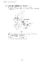
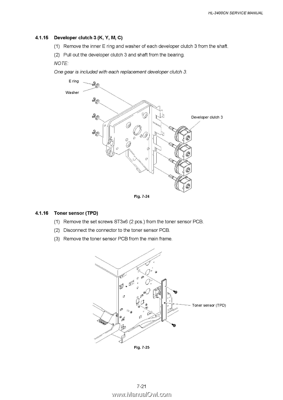
HL-3400CN SERVICE MANUAL 4.1.15 Developer clutch 3 (K, Y, M, C) (1) Remove the inner E ring and washer of each developer clutch 3 from the shaft. (2) Pull out the developer clutch 3 and shaft from the bearing. NOTE: One gear is included with each replacement developer clutch 3. E ring Washer 9 0 Developer clutch 3 0 I I Fig. 7-24 4.1.16 Toner sensor (TPD) (1) Remove the set screws ST3x6 (2 pcs.) from the toner sensor PCB. (2) Disconnect the connector to the toner sensor PCB. (3) Remove the toner sensor PCB from the main frame. Q. @ Fig. 7-25 7-21 Toner sensor (TPD)
-
 1
1 -
2
-
3
-
4
-
5
-
6
-
7
-
8
-
9
-
10
-
11
-
12
-
13
-
14
-
15
-
16
-
17
-
18
-
19
-
20
-
21
-
22
-
23
-
24
-
25
-
26
-
27
-
28
-
29
-
30
-
31
-
32
-
33
-
34
-
35
-
36
-
37
-
38
-
39
-
40
-
41
-
42
-
43
-
44
-
45
-
46
-
47
-
48
-
49
-
50
-
51
-
52
-
53
-
54
-
55
-
56
-
57
-
58
-
59
-
60
-
61
-
62
-
63
-
64
-
65
-
66
-
67
-
68
-
69
-
70
-
71
-
72
-
73
-
74
-
75
-
76
-
77
-
78
-
79
-
80
-
81
-
82
-
83
-
84
-
85
-
86
-
87
-
88
-
89
-
90
-
91
-
92
-
93
-
94
-
95
-
96
-
97
-
98
-
99
-
100
-
101
-
102
-
103
-
104
-
105
-
106
-
107
-
108
-
109
-
110
-
111
-
112
-
113
-
114
-
115
-
116
-
117
-
118
-
119
-
120
-
121
-
122
-
123
-
124
-
125
-
126
-
127
-
128
-
129
-
130
-
131
-
132
-
133
-
134
-
135
-
136
-
137
-
138
-
139
-
140
-
141
-
142
-
143
-
144
-
145
-
146
-
147
-
148
-
149
-
150
-
151
-
152
-
153
-
154
-
155
-
156
-
157
-
158
-
159
-
160
-
161
-
162
-
163
-
164
-
165
-
166
-
167
-
168
-
169
-
170
-
171
-
172
-
173
-
174
-
175
-
176
-
177
-
178
-
179
-
180
-
181
-
182
-
183
-
184
-
185
-
186
-
187
-
188
-
189
-
190
-
191
-
192
-
193
-
194
-
195
-
196
-
197
-
198
-
199
-
200
-
201
-
202
-
203
-
204
-
205
-
206
-
207
-
208
-
209
-
210
-
211
-
212
-
213
-
214
-
215
-
216
-
217
-
218
-
219
-
 220
220 -
 221
221 -
 222
222 -
 223
223 -
 224
224 -
 225
225 -
 226
226 -
 227
227 -
 228
228 -
 229
229 -
 230
230 -
231
-
232
-
233
-
234
-
235
-
236
-
237
-
238
-
239
-
240
-
241
-
242
-
243
-
244
-
245
-
246
-
247
-
248
-
249
-
250
-
251
-
252
-
253
-
254
-
255
-
256
-
257
-
258
-
259
-
260
-
261
-
262
-
263
-
264
-
265
-
266
-
267
-
268
-
269
-
270
-
271
-
272
-
273
-
274
-
275
-
276
-
277
-
278
-
279
-
280
-
281
-
282
-
283
-
284
-
285
-
286
-
287
-
288
-
289
-
290
-
291
-
292
-
293
-
294
-
295
-
296
-
297
-
298
-
299
-
300
-
301
-
302
-
303
-
304
-
305
-
306
-
307
-
308
-
309
-
310
-
311
-
312
-
313
-
314
-
315
-
316
-
317
-
318
-
319
-
320
-
321
-
322
-
323
-
324
-
325
-
326
-
327
-
328
-
329
-
330
-
331
-
332
-
333
-
334
-
335
-
336
-
337
-
338
-
339
-
340
-
341
-
342
-
343
-
344
-
345
-
346
-
347
 |
 |
HL-3400CN
SERVICE
MANUAL
4.1.15
Developer
clutch
3
(K,
Y,
M,
C)
(1)
Remove
the
inner
E
ring
and
washer
of
each
developer
clutch
3
from
the
shaft.
(2)
Pull
out
the
developer
clutch
3
and
shaft
from
the
bearing.
NOTE:
One
gear
is
included
with
each
replacement
developer
clutch
3.
E
ring
Washer
0
9
0
Fig.
7-24
I
I
Developer
clutch
3
4.1.16
Toner
sensor
(TPD)
(1)
Remove
the
set
screws
ST3x6
(2
pcs.)
from
the
toner
sensor
PCB.
(2)
Disconnect
the
connector
to
the
toner
sensor
PCB.
(3)
Remove
the
toner
sensor
PCB
from
the
main
frame.
Q.
@
Toner
sensor
(TPD)
Fig.
7-25
7-21