Brother International HL-3400CN Service Manual - Page 244
connector
 |
UPC - 012502526223
View all Brother International HL-3400CN manuals
Add to My Manuals
Save this manual to your list of manuals |
Page 244 highlights
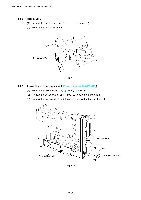
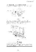
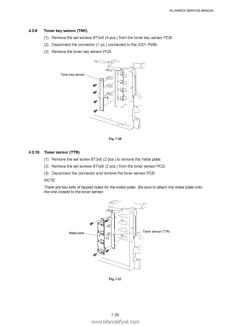
HL-3400CN SERVICE MANUAL 4.3.9 Toner key sensor (TNK) (1) Remove the set screws ST3x6 (4 pcs.) from the toner key sensor PCB. (2) Disconnect the connector (1 pc.) connected to the IOD1 PWB. (3) Remove the toner key sensor PCB. Toner key sensor Fig. 7-56 4.3.10 Toner sensor (TTR) (1) Remove the set screw ST3x6 (2 pcs.) to remove the metal plate. (2) Remove the set screws ST3x6 (2 pcs.) from the toner sensor PCB. (3) Disconnect the connector and remove the toner sensor PCB. NOTE: There are two sets of tappedholes for the metalplate. Be sure to attach the metal plate onto the one closest to the toner sensor. Metal plate Toner sensor (TTR) Fig. 7-57 7-39
-
 1
1 -
2
-
3
-
4
-
5
-
6
-
7
-
8
-
9
-
10
-
11
-
12
-
13
-
14
-
15
-
16
-
17
-
18
-
19
-
20
-
21
-
22
-
23
-
24
-
25
-
26
-
27
-
28
-
29
-
30
-
31
-
32
-
33
-
34
-
35
-
36
-
37
-
38
-
39
-
40
-
41
-
42
-
43
-
44
-
45
-
46
-
47
-
48
-
49
-
50
-
51
-
52
-
53
-
54
-
55
-
56
-
57
-
58
-
59
-
60
-
61
-
62
-
63
-
64
-
65
-
66
-
67
-
68
-
69
-
70
-
71
-
72
-
73
-
74
-
75
-
76
-
77
-
78
-
79
-
80
-
81
-
82
-
83
-
84
-
85
-
86
-
87
-
88
-
89
-
90
-
91
-
92
-
93
-
94
-
95
-
96
-
97
-
98
-
99
-
100
-
101
-
102
-
103
-
104
-
105
-
106
-
107
-
108
-
109
-
110
-
111
-
112
-
113
-
114
-
115
-
116
-
117
-
118
-
119
-
120
-
121
-
122
-
123
-
124
-
125
-
126
-
127
-
128
-
129
-
130
-
131
-
132
-
133
-
134
-
135
-
136
-
137
-
138
-
139
-
140
-
141
-
142
-
143
-
144
-
145
-
146
-
147
-
148
-
149
-
150
-
151
-
152
-
153
-
154
-
155
-
156
-
157
-
158
-
159
-
160
-
161
-
162
-
163
-
164
-
165
-
166
-
167
-
168
-
169
-
170
-
171
-
172
-
173
-
174
-
175
-
176
-
177
-
178
-
179
-
180
-
181
-
182
-
183
-
184
-
185
-
186
-
187
-
188
-
189
-
190
-
191
-
192
-
193
-
194
-
195
-
196
-
197
-
198
-
199
-
200
-
201
-
202
-
203
-
204
-
205
-
206
-
207
-
208
-
209
-
210
-
211
-
212
-
213
-
214
-
215
-
216
-
217
-
218
-
219
-
220
-
221
-
222
-
223
-
224
-
225
-
226
-
227
-
228
-
229
-
230
-
231
-
232
-
233
-
234
-
235
-
236
-
237
-
238
-
 239
239 -
 240
240 -
 241
241 -
 242
242 -
 243
243 -
 244
244 -
 245
245 -
 246
246 -
 247
247 -
 248
248 -
 249
249 -
250
-
251
-
252
-
253
-
254
-
255
-
256
-
257
-
258
-
259
-
260
-
261
-
262
-
263
-
264
-
265
-
266
-
267
-
268
-
269
-
270
-
271
-
272
-
273
-
274
-
275
-
276
-
277
-
278
-
279
-
280
-
281
-
282
-
283
-
284
-
285
-
286
-
287
-
288
-
289
-
290
-
291
-
292
-
293
-
294
-
295
-
296
-
297
-
298
-
299
-
300
-
301
-
302
-
303
-
304
-
305
-
306
-
307
-
308
-
309
-
310
-
311
-
312
-
313
-
314
-
315
-
316
-
317
-
318
-
319
-
320
-
321
-
322
-
323
-
324
-
325
-
326
-
327
-
328
-
329
-
330
-
331
-
332
-
333
-
334
-
335
-
336
-
337
-
338
-
339
-
340
-
341
-
342
-
343
-
344
-
345
-
346
-
347
 |
 |
HL-3400CN
SERVICE
MANUAL
4.3.9
Toner
key
sensor
(TNK)
(1)
Remove
the
set
screws
ST3x6
(4
pcs.)
from
the
toner
key
sensor
PCB.
(2)
Disconnect
the
connector
(1
pc.)
connected
to
the
IOD1
PWB.
(3)
Remove
the
toner
key
sensor
PCB.
Toner
key
sensor
Fig.
7-56
4.3.10
Toner
sensor
(TTR)
(1)
Remove
the
set
screw
ST3x6
(2
pcs.)
to
remove
the
metal
plate.
(2)
Remove
the
set
screws
ST3x6
(2
pcs.)
from
the
toner
sensor
PCB.
(3)
Disconnect
the
connector
and
remove
the
toner
sensor
PCB.
NOTE:
There
are
two
sets
of
tapped
holes
for
the
metal
plate.
Be
sure
to
attach
the
metal
plate
onto
the
one
closest
to
the
toner
sensor.
Metal
plate
Fig.
7-57
Toner
sensor
(TTR)
7-39