Brother International HL-3400CN Service Manual - Page 132
Control, Panel, Operation, Address, Write
 |
UPC - 012502526223
View all Brother International HL-3400CN manuals
Add to My Manuals
Save this manual to your list of manuals |
Page 132 highlights
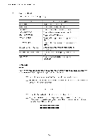
CHAPTER 5 CONTROL PANEL OPERATION 2.4 DRAM Test Mode This mode tests the memory and optional DIM Ms installed on the main (video controller) PCB. To start the test program: (1) While holding down the V button, turn on the power. "DRAM CHECK START" will be displayed. Press the Continue button to start the DRAM check. (2) The LCD will display "START DRAM TEST", and the Data LED blinks. (3) On satisfactory completion of all the RAM tests, the LCD will display: "DRAM OK!!", and the Alarm LED is on. (4) If any DRAM error has occurred, the LCD will display a fail message as follows; 1' RAM Address I' WRITE data -0.- 1 . READ data (5) Enter the hidden menu mode as follows to confirm the current memory map; i) Press the Form Feed, Mode and Continue buttons at the same time in the off-line status. ii) The LCD will display "HIDDEN PANEL" iii) Select the "DRAM ADDRESS" menu using the scroll buttons. iv) Whenever the Set button is pressed, the LCD will display "START DRAM TEST" , and the Data LED blinks (Return to (2)). (6) If a DIM M has an error, replace the DIMM corresponding to the above memory map information. If the DRAM on the main PCB has an error, replace referring to the table below; Lower order address (where an error occurs) DRAM chip to be replaced *A *B 0, 4, 8, C #8 #6 1, 5, 9, D #5 #1 2, 6, A, E #14 #11 3, 7, B, F #123 #16 Address A: 2000-0000 - 27FF-FFFF B: 2800-0000 - 2FFF-FFFF *A: If the upper digit of the data is wrong. *B: If the lower digit of the data is wrong. *NOTE: • There may be a case where the above sequence does not work correctly due to complete RAM failure, or in faulty assembly such as a solder bridge or ineffective soldering etc. 5-10
-
 1
1 -
2
-
3
-
4
-
5
-
6
-
7
-
8
-
9
-
10
-
11
-
12
-
13
-
14
-
15
-
16
-
17
-
18
-
19
-
20
-
21
-
22
-
23
-
24
-
25
-
26
-
27
-
28
-
29
-
30
-
31
-
32
-
33
-
34
-
35
-
36
-
37
-
38
-
39
-
40
-
41
-
42
-
43
-
44
-
45
-
46
-
47
-
48
-
49
-
50
-
51
-
52
-
53
-
54
-
55
-
56
-
57
-
58
-
59
-
60
-
61
-
62
-
63
-
64
-
65
-
66
-
67
-
68
-
69
-
70
-
71
-
72
-
73
-
74
-
75
-
76
-
77
-
78
-
79
-
80
-
81
-
82
-
83
-
84
-
85
-
86
-
87
-
88
-
89
-
90
-
91
-
92
-
93
-
94
-
95
-
96
-
97
-
98
-
99
-
100
-
101
-
102
-
103
-
104
-
105
-
106
-
107
-
108
-
109
-
110
-
111
-
112
-
113
-
114
-
115
-
116
-
117
-
118
-
119
-
120
-
121
-
122
-
123
-
124
-
125
-
126
-
 127
127 -
 128
128 -
 129
129 -
 130
130 -
 131
131 -
 132
132 -
 133
133 -
 134
134 -
 135
135 -
 136
136 -
 137
137 -
138
-
139
-
140
-
141
-
142
-
143
-
144
-
145
-
146
-
147
-
148
-
149
-
150
-
151
-
152
-
153
-
154
-
155
-
156
-
157
-
158
-
159
-
160
-
161
-
162
-
163
-
164
-
165
-
166
-
167
-
168
-
169
-
170
-
171
-
172
-
173
-
174
-
175
-
176
-
177
-
178
-
179
-
180
-
181
-
182
-
183
-
184
-
185
-
186
-
187
-
188
-
189
-
190
-
191
-
192
-
193
-
194
-
195
-
196
-
197
-
198
-
199
-
200
-
201
-
202
-
203
-
204
-
205
-
206
-
207
-
208
-
209
-
210
-
211
-
212
-
213
-
214
-
215
-
216
-
217
-
218
-
219
-
220
-
221
-
222
-
223
-
224
-
225
-
226
-
227
-
228
-
229
-
230
-
231
-
232
-
233
-
234
-
235
-
236
-
237
-
238
-
239
-
240
-
241
-
242
-
243
-
244
-
245
-
246
-
247
-
248
-
249
-
250
-
251
-
252
-
253
-
254
-
255
-
256
-
257
-
258
-
259
-
260
-
261
-
262
-
263
-
264
-
265
-
266
-
267
-
268
-
269
-
270
-
271
-
272
-
273
-
274
-
275
-
276
-
277
-
278
-
279
-
280
-
281
-
282
-
283
-
284
-
285
-
286
-
287
-
288
-
289
-
290
-
291
-
292
-
293
-
294
-
295
-
296
-
297
-
298
-
299
-
300
-
301
-
302
-
303
-
304
-
305
-
306
-
307
-
308
-
309
-
310
-
311
-
312
-
313
-
314
-
315
-
316
-
317
-
318
-
319
-
320
-
321
-
322
-
323
-
324
-
325
-
326
-
327
-
328
-
329
-
330
-
331
-
332
-
333
-
334
-
335
-
336
-
337
-
338
-
339
-
340
-
341
-
342
-
343
-
344
-
345
-
346
-
347
 |
 |
