Brother International HL-3400CN Service Manual - Page 223
to remove
 |
UPC - 012502526223
View all Brother International HL-3400CN manuals
Add to My Manuals
Save this manual to your list of manuals |
Page 223 highlights
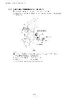
HL-3400CN SERVICE MANUAL 4.1.12 Paper feeding clutch / EP3 gear assembly (1) Remove the set screw ST3x6 (1 pc.) to remove the metal retainer. (2) Remove the outer plastic C ring from the shaft. (3) Remove the paper feeding clutch from the shaft. (4) Remove the set screw ST3x6 (2 pcs.) from the EP3 gear assembly. a 0 ere EP3 gear assembly Fig. 7-21 Paper feeding clutch 11L-C ring Metal retainer "re 4.1.13 WT holder assembly (1) Open the front cover. (2) Remove the set screw ST3x6 (1 pc.) from the frame. (3) Remove the set screw ST3x6 (1 pc.) from the WT holder assembly and remove the holder from the frame. Note that the waste toner sensor is assembled onto the WT holder assembly. 0 0 oo 0 0 0 a" Fig. 7-22 WT holder assembly 7-19
-
 1
1 -
2
-
3
-
4
-
5
-
6
-
7
-
8
-
9
-
10
-
11
-
12
-
13
-
14
-
15
-
16
-
17
-
18
-
19
-
20
-
21
-
22
-
23
-
24
-
25
-
26
-
27
-
28
-
29
-
30
-
31
-
32
-
33
-
34
-
35
-
36
-
37
-
38
-
39
-
40
-
41
-
42
-
43
-
44
-
45
-
46
-
47
-
48
-
49
-
50
-
51
-
52
-
53
-
54
-
55
-
56
-
57
-
58
-
59
-
60
-
61
-
62
-
63
-
64
-
65
-
66
-
67
-
68
-
69
-
70
-
71
-
72
-
73
-
74
-
75
-
76
-
77
-
78
-
79
-
80
-
81
-
82
-
83
-
84
-
85
-
86
-
87
-
88
-
89
-
90
-
91
-
92
-
93
-
94
-
95
-
96
-
97
-
98
-
99
-
100
-
101
-
102
-
103
-
104
-
105
-
106
-
107
-
108
-
109
-
110
-
111
-
112
-
113
-
114
-
115
-
116
-
117
-
118
-
119
-
120
-
121
-
122
-
123
-
124
-
125
-
126
-
127
-
128
-
129
-
130
-
131
-
132
-
133
-
134
-
135
-
136
-
137
-
138
-
139
-
140
-
141
-
142
-
143
-
144
-
145
-
146
-
147
-
148
-
149
-
150
-
151
-
152
-
153
-
154
-
155
-
156
-
157
-
158
-
159
-
160
-
161
-
162
-
163
-
164
-
165
-
166
-
167
-
168
-
169
-
170
-
171
-
172
-
173
-
174
-
175
-
176
-
177
-
178
-
179
-
180
-
181
-
182
-
183
-
184
-
185
-
186
-
187
-
188
-
189
-
190
-
191
-
192
-
193
-
194
-
195
-
196
-
197
-
198
-
199
-
200
-
201
-
202
-
203
-
204
-
205
-
206
-
207
-
208
-
209
-
210
-
211
-
212
-
213
-
214
-
215
-
216
-
217
-
 218
218 -
 219
219 -
 220
220 -
 221
221 -
 222
222 -
 223
223 -
 224
224 -
 225
225 -
 226
226 -
 227
227 -
 228
228 -
229
-
230
-
231
-
232
-
233
-
234
-
235
-
236
-
237
-
238
-
239
-
240
-
241
-
242
-
243
-
244
-
245
-
246
-
247
-
248
-
249
-
250
-
251
-
252
-
253
-
254
-
255
-
256
-
257
-
258
-
259
-
260
-
261
-
262
-
263
-
264
-
265
-
266
-
267
-
268
-
269
-
270
-
271
-
272
-
273
-
274
-
275
-
276
-
277
-
278
-
279
-
280
-
281
-
282
-
283
-
284
-
285
-
286
-
287
-
288
-
289
-
290
-
291
-
292
-
293
-
294
-
295
-
296
-
297
-
298
-
299
-
300
-
301
-
302
-
303
-
304
-
305
-
306
-
307
-
308
-
309
-
310
-
311
-
312
-
313
-
314
-
315
-
316
-
317
-
318
-
319
-
320
-
321
-
322
-
323
-
324
-
325
-
326
-
327
-
328
-
329
-
330
-
331
-
332
-
333
-
334
-
335
-
336
-
337
-
338
-
339
-
340
-
341
-
342
-
343
-
344
-
345
-
346
-
347
 |
 |

HL-3400CN
SERVICE
MANUAL
4.1.12
Paper
feeding
clutch
/
EP3
gear
assembly
(1)
Remove
the
set
screw
ST3x6
(1
pc.)
to remove
the
metal
retainer.
(2)
Remove
the
outer
plastic
C
ring
from
the
shaft.
(3)
Remove
the
paper
feeding
clutch
from
the
shaft.
(4)
Remove
the
set
screw
ST3x6
(2
pcs.)
from
the
EP3
gear
assembly.
a
e
re
0
"re
EP3
gear
assembly
Fig.
7-21
Paper
feeding
clutch
11L
—
C
ring
Metal
retainer
4.1.13
WT
holder
assembly
(1)
Open
the
front
cover.
(2)
Remove
the
set
screw
ST3x6
(1
pc.)
from
the
frame.
(3)
Remove
the
set
screw
ST3x6
(1
pc.)
from
the
WT
holder
assembly
and
remove
the
holder
from
the
frame.
Note
that
the
waste
toner
sensor
is
assembled
onto
the
WT
holder
assembly.
0
oo
0
0
0
a"
Fig.
7-22
0
WT
holder
assembly
7-19